

Two images taken 5 steps apart.
By Ekapol Chuangsuwanich
Topics
Motivation
What are Joiners?
Implementation
Feature detection
Global Alignment
Ordering
Readjustment
GUI - Reordering
Results
Reference
In project 4, we have implemented a program that can combines multiple images to form a panorama. However, in order for the algorithm to work, the images need to be taken from a single view point. If the images are not taken from the same view point, there will be inconsistencies in the final mosaic as shown
Two images taken 5 steps apart.

Final panorama using the algorithm in project 4. Note how objects that are close
to the photographer are not consistent.
In this project, I will implement an art technique called "joiners" in order to produce a mosaic that contains more than a single view point and still looks pleasing to the eyes.
Joiners is a term used by David Hockney who is considered the pioneer of the the technique. Joiners is done by layering multiple photographs taken from multiple view points to form a composite image. Due to the multiple view points that can be seen in joiners, the composite can be very compelling.

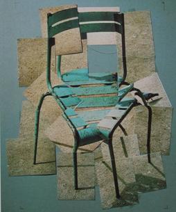
Examples of joiners by David Hockney.
Currently, joiners are popular on the image sharing site Flickr. However, the technique requires a lot of time and effort to align the images. A joiner containing 10-15 images can easily take up 30 minutes to make. For artists, the amount of time might be acceptable. What if you want to just show your friends a panoramic scene taken from a trip to Europe but the software package that comes with your camera cannot align your photos because they are taken from multiple view points. In this case, 30 minutes to do a composite manually is impractical. Thus, we need a software to create joiners automatically. This can also help artists to get an initial starting point which will reduce the amount of time they need to spend to produce joiners.
An algorithm to produce joiners automatically is proposed in "Automating Joiners" by Lihi Zelnik-Manor and Pietro Perona. This project does not implement the algorithm exactly as mentioned in the paper, but use it as a guideline on how each steps should work. The overall framework of the algorithm can be broken into 4 main steps as follow
1. Features detection
2. Global Alignment
3. Ordering
4. Readjustment
Find the feature correspondence between each pair of images. The feature used is Lowe's SIFT features. A pair of a feature points from 2 images is a match if the ratio between the 1st nearest neighbor over the 2nd nearest neighbor is greater than 0.6.
This is the result of the feature extraction and matching. As you can see, there are some false matches.

The outliers are removed by using RANSAC. A match will be considered as an outlier if the distance between the transformed point and the intended point is larger than 30 pixels. This number is much bigger than the number used in project 4 because the 2 images cannot be transform into each other perfectly due to the difference in view point.
As shown below, RANSAC can remove the 2 incorrect matches.

Instead of using homographic transform as in project 4, we want to use similarity transform to mimic the effect of joiners instead. A similarity transform can be considered as a combination of scaling (c), rotation (R), and transition (T). Given a set of feature correspondence coordinates X and Y, the goal for this step is to find the c, R, and T such that E = (Y - (cRX+T))^2 is minimized.
The "Automating Joiners" paper uses Levenberg-Marquardt algorithm to minimized the function. However, due to lack of documentation in the original paper, I chose to implement this step differently. I implement the method described in "Least-Squares Estimation of Transformation Parameters Between Two Points Patterns" by S. Umeyama. According to the Umeyama, c, R, and T can be found by using the following equations

Using the transform, we can compute for the best alignment of all the images.
Here is an example of this stage output
Input images


Global Aligned

The output shown is ordered by the ordering of the input image.
After the alignment, we need to reorder the images so that the image looks "nice." We want the ordering such that there are the least amount of inconsistencies. Since each image will always be consistent (a real photo), we can limit the problem to just the borders between images. The original paper suggest many ways to quantify which ordering is better. For this project, I choose to minimize the gradient across the boundaries because of ease in implementation and the paper suggests that this method produce good results.
After the ordering we get a better looking composite.

Even though the picture looks better than the previous step. There are some glaring inconsistencies in the image such as the pole on the right side is completely off.
The reason that the pole is off is because the similarity transform is trying to minimize the distance between the feature points equally across the whole image. However, the points that are really important to us are the points near the boundaries. Using this observation, we can realign the image by giving more weight to the points near the borders. However, due to the limitation of the algorithm I use to find the transform, I cannot use different weights for different points. Thus, the new transform is calculated by picking the 10 points closest to the boundaries instead.


Left: All feature correspondence between the 2 image. Right: 10
closest points.
Red points are the feature points for the lower image. Green points are the
feature points for the upper image.
After readjustment, we got our final output.

The 4 steps above usually produce good joiners. However, it can be easily made better by very minimal user input. The automate ordering might looks nicest but might not have the effect we want. Thus, the user should be able to specify a new ordering for the composite instead of the one suggested.
Below shows an example when the "optimal" ordering might not be the best


Top: manual ordering. Bottom: "optimal" ordering. In this case
the user wants to stimulate the effect of the same person being in different
places.
In order for easy reordering, I write a simple GUI in MATLAB. This GUI lets the user reorder the image in the composite just as they wish. Here is a picture of the GUI.

"Load data" loads the data of the current work for reordering.
The list box shows the filenames ordered by the current ordering. The
first on the list is the top most picture in the composite.
"Up"/"Down" moves the selected picture one step higher/lower in the
ordering.
"View" combine the images by the ordering in the list box.
The upper picture is the output image.
The lower left picture is the selected picture in normal coordinates
The lower right picture is the selected picture in the composite
coordinates
"I'm feeling lucky!" randomizes the ordering and show the result.
"I'm done!" saves the current result and exit the GUI.
Note that it might be better to run the reordered image through step 4 again for best results.
Shown below are the results from my implementation of the algorithm.
Note: these pictures are shrunk in the html code to the size that look nice on my laptop. If you want to look at a bigger size, you can do so be viewing the images by themselves.


Left: Before ordering. Right: end result. I put them both here
because I really like the effect of the left picture.


Zelnik-Manor, Lihi and Perona, Pietro. “Automating Joiners.”
http://www.vision.caltech.edu/lihi/Demos/AutoJoiners.html
Umeyama, Shinji. “Least-Squares Estimation of Transformation Parameters Between
Two Point Patterns.” IEEE Transactions on Pattern Analysis and Machine
Intelligence. Vol. 13. No 4. April 1991
Brown, M. “Recognising Panoramas.”
http://research.microsoft.com/~brown/papers/iccv2003.pdf
Lowe, David. “SIFT Keypoint Detector.”
http://www.cs.ubc.ca/~lowe/keypoints/