SolidWorks Intro Part 4
Dave Touretzky
- Up to now we've been restricted to making planar parts using extruded base and extruded cut.
- Let's look at some features that produce three-dimensional shapes.
REVOLVE 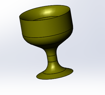
- Make a new part.
- Select the Revolved Base feature on the Front Plane.
- Draw the cross-section of a goblet.
- Select the midline as the axis of revolution and complete the feature.
- Apply a large fillet to the spot where the stem meets the cup.
- Apply smaller fillets to other edges, as desired.
LOFT and SHELL 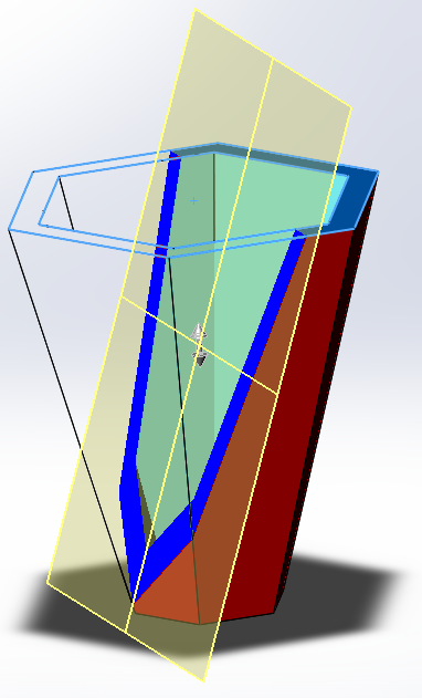
- Make a new part.
- Switch to the Sketch tab and click on "Sketch" to create a naked sketch; put your sketch on the Top Plane.
- Draw a hexagon centered on the origin.
- Give the top line of the hexagon the Horizontal property.
- Dimension the hexagon to a 2 inch diameter.
- Exit the sketch.
- Switch to the Features tab.
- Under Reference Geometry, make a new plane.
- Open the feature tree in the main window to reveal the existing planes.
- Specify that your plane is relative to the Top Plane, with an offset of 6 inches.
- Click OK to complete the plane.
- Go to the Sketch tab.
- Click on your new Plane 1.
- Click on the Sketch button to make a new sketch on Plane 1.
- Draw a hexagon centered on the origin, concentric with but larger than the earlier one.
- Give the matching edge the Horizontal property.
- Dimension the hexagon to a 5 inch diameter.
- Exit the sketch.
- Go back to the Features tab and notice that Lofted Base is un-grayed.
- Select Lofted Base.
- In the Profiles box, click on the top left point in each of your two sketches.
- Click OK to complete the loft.
- Click on Shell in the Features tab.
- Click on the large hexagon face.
- Click OK to complete the shell.
- Right click on Plane1 in the feature manager tree and select Hide.
- Color the Loft feature, not the whole part.
- Color the Shell feature a different color.
- Click on the Section View button and drag the arrow.
- Click OK to complete the section view.
- Click the Section View button again to return to a normal view.
- Save your part as Vase.SLDPRT.
The Flex Tool: TWIST 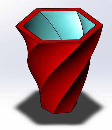
- Start with the vase you created in the previous exercise.
- Click on the Flex feature in the Features tab.
- If you don't have Flex in your features tab, go to the top
pulldown menu and click on Insert, select "Features", and then select
"Flex".
- Notice that Flex can do four different things: twist, bend, taper, or stretch.
- Click anywhere on the vase.
- Click on the "Twisting" radio button.
- The twist axis is shown as a dashed blue line.
- You can use the triad (three rings) to rotate the twist axis, but
you probably don't want to do this.
- Click on the red trim plane and drag it to apply a twist of about
120 degrees. You can read the twist angle in the parameter box on the
left.
- Click OK to complete the twist action.
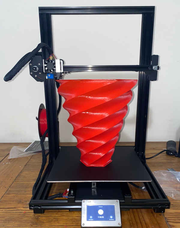
- Edit the feature again and try some other twist values: 180 degrees, and 520 degrees.
The Flex Tool: BEND 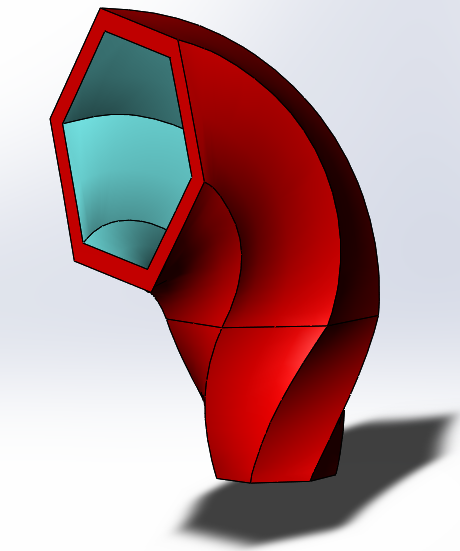
- Create another Flex feature.
- If you don't have Flex in your Features toolbar, you can add
it by selecting Tools from the top pulldown menu, then click on
"Customize"; select the "Commands" tab; click on the "Features" menu
item; and finally, drag the Flex icon onto the Features toolbar. Then
click "OK".
- Click anywhere on the case.
- Select the Bending radio button.
- The bend axis is shown as a dashed red line.
- Move the bottom trim-plane one third of the way up the vase.
- Right click on the Triad and select "Move triad to Plane 1" (the bottom plane).
- Click on the red trim plane and drag it to bend the vase to about 75 degrees.
- Click OK.
- If you get a self-intersection error, move the trim plane down or reduce the bend angle.
More Flex Tool 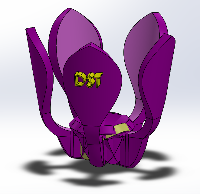
- Make a new part.
- Make an extruded base on the top plane.
- Draw a circle centered on the origin. Dimension the diameter to
0.3 inches and extrue to a depth of 0.1 inches.
- Create a new Extruded Base on the Top Plane.
- Draw a 1.5 inch centerline upward from the origin.
- Draw a vertical line starting to the left of the origin and extending upward; dimension it to 0.35 inches.
- Dimension the horizontal distance from the vertical line to the centerline at 0.05 inches.
- Make sure the bottom of the vertical line is horizontal to the origin.
- Add a short horizontal line connecting the bottom of the vertial line to the origin.
- Add a three-point spline whose first point is the top of the centerline, and whose other two points are to the left of the centerline.
- Snap the bottom point of the spline to the top of the vertical line.
- Adjust the spline control points to make a leaf shape.
- Mirror the spline and the two lines about the centerline.
- Uncheck the "merge" box and extrude to a depth of 0.1 inches.
- Go to Insert > Features and insert a Flex feature.
- Set the fex type to "bend".
- Click on the extrusion.
- Set the triad y angle to 90 degrees.
- Move the trim planes in so we don't bend the edges of the leaf.
- Set the triad y value to 0.2 inches
- Set the bend angle to -84 degrees.
- Click on the green checkmark.
- Insert another Flex feature.
- Set the type to "bend" and click on the extrusion.
- Click on the triad's Z arrow and slide the triad left to z = -0.35 inches.
- Click on the triad's Y arrow and slide the triad up to 0.25 inches.
- Put the red trim plane at the triad.
- Move the green trim plane to the top of the stem.
- Set the bend angle to -90 degrees.
- Click on the green checkmark.
- Make a circular pattern. Select "bodies" and select the leaf as
the feature to pattern and the edge of the circle as the
direction. Set the number of instances to 5.
- Create a third Flex feature.
- Set the type to "Stretch".
- Select all the leaves as bodies to stretch (use shift-click to add each leaf).
- Move the trim planes so we stretch only the stem portion.
- Stretch the flower a bit.
- Color the flower. Color the inner face of each petal a different shade.
- Save your part as Flower.SLDPRT.
Embossed Text On A Curved Surface
- We're going to emboss our initials onto one petal of the flower.
- Go to the Features tab, and under Reference Geometry, click on Plane.
- For the first reference, choose the back face of a petal.
- For the second reference, choose the midpoint of the bend line on the stem.
- Click OK to complete the reference plane.
- With the plane selected, go to the Sketch tab and click the Sketch button to make a new
sketch on that reference plane.
- Draw a construction line as the baseline for your text.
- Click on the Text tool.
- In the Curves box, select the construction line.
- Type your initials in the Text box.
- Uncheck the "Use document font" option.
- Click on the Font button and set the font size to 0.1 inches.
- Leave the font name as "Century Gothic". Not all fonts work for embossing, but this one does.
- Click OK to complete the text object.
- Adjust the line endpoints as necessary to position the text.
- Exit the sketch.
- With the new sketch selected, go to the Features tab and click on Extruded Base.
- Change the Direction1 value from "Blind" to "Mid-Plane".
- Set the extrusion depth to 0.2 inches.
- Click OK to complete the extrusion.
- Save your part.
|


