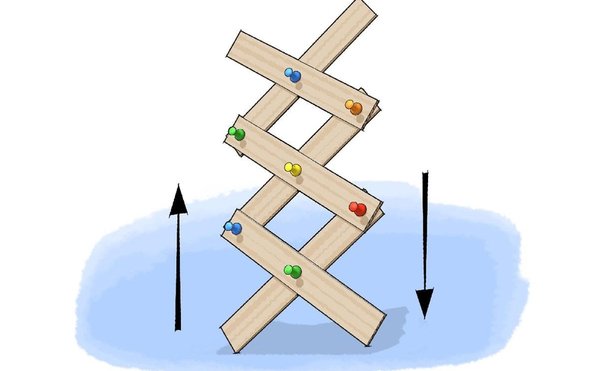
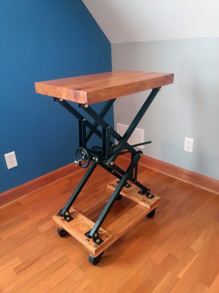
Scissors Linkage

Backing Plate
- Create a new part.
- Create an Extruded Base on the Front plane.
- Draw a 6 inch by 6 inch square in the sketch, and extrude to a depth of 1/8 inch.
- Edit the sketch and place a circle inside the square; dimension it to 1/8 inch diameter.
- Set the dimension precision to three digits (.123).
- Place a second circle two inches to the right of the first one.
- Make the circles Equal.
- Exit the sketch and color the part brown.
- Save the part as BackingPlate.SLDPRT.
Lever
- Create a new part.
- Create an Extruded Base on the Front plane.
- Draw a horizontal slot starting at the origin.
- Dimension the slot radius to 1/8 inch. (Note that this is a radius, not a diameter.)
- Set the dimension precision to three digits (.123).
- Dimension the slot length to 3 inches.
- Draw a circle at the center of each arc, and at the midpoint of the slot.
- Make all the circles Equal.
- Dimension the left circle to a diameter of 1/8 inch.
- Set the dimension precision to three digits (.123).
- Exit the sketch and extrude to a depth of 1/8 inch.
- Color the entire part red.
- Save the part as Lever.SLDPRT.
Spacer
- We don't want the lever to rest against the backing plate because
that won't leave room for the fasteners. Therefore, we need to create
a spacer.
- Start a new part and create an Extruded Base on the Front plane.
- Draw a circle centered on the origin with diameter 1/4 inch.
- Draw a circle inside it, centered on the origin, with diameter 1/8 inch.
- Exit the sketch and set the extrude depth to 1/8 inch.
- Save you part as Spacer.SLDPRT.
First Assembly
- Create a new Assembly.
- Insert the BackingPlate as the first part. Note that it is Fixed (f) by default.
- Insert a Spacer as the second part.
- Mate the bottom edge of the hole in the spacer to the left hole in the backing plate. Because the diameters are equal, this will
be a Coincident mate.
- Insert a Lever as the third part.
- Mate the center hole of the lever to the spacer by selecting the back edge of the lever hole and the front edge
of the spacer hole. You should
be able to use a Coincident mate.
- Now you can click and drag on the lever and it will pivot about the center hole, like a real lever.
- Insert a second Spacer and Lever.
- Mate the second spacer's hole to the right hole in the backing plate.
- Mate the second level's middle hole to the second spacer.
- Note that the second lever also pivots, but when the two levers collide they pass right through each other.
Scissors Mechanism
- Insert a third lever.
- Connect the third lever to the first one by mating the bottom
edge of the third lever's center hole to the top edge of the first
lever's center hole.
- Mate the bottom edge of the third lever's right hole to the top
edge of the second lever's left hole.
- Insert a fourth lever.
- Connect the fourth Lever to the second one by mating the bottom
edge of the fourth lever's center hole to the top edge of the second
lever's center hole.
- Mate the bottom edge of the fourth Lever's left hole to the top
edge of the first lever's right hole.
- Note that we cannot move the mechanism now. That is because it is
fixed to the backing plate in two locations.
- Edit the second lever's mates and remove its coincident mate to the backing plate.
- Now we can move any lever and the entire mechanism changes shape.
But it's underconstrained so it moves in a cockeyed fashion.
Constrained Motion: Slot Mate
- Return to the BackingPlate part and edit the sketch.
- Delete the right circle.
- Draw a horizontal slot to the right of the remaining circle.
- Add a Coincident relation between the center of the circle and the construction line of the slot, if it's not already there.
- Dimension the slot radius to 1/16 inch.
- Set the dimension precision to 4 digits (.1234).
- Dimension the length of the slot's construction line to 2.5 inches.
- Dimension the distance between the center of the circle and the
left edge of the slot's construction line to 0.25 inches.
- Save the part and return to the assembly.
- Click on the mate tool.
- Scroll down to the Mechanical Mates section and open it.
- Select Slot Mate.
- In the graphics window, select the face of the third lever's hole, then select one of the long faces of the slot in the backing plate.
- Click the green check mark to accept the mate.
- Now moving any of the levers causes constrained motion of the
mechanism: it's restricted to moving along the path of the slot.
- Add two more levers to extend the scissors. You do not need
another slot mate, just four coincident mates.
- Save the assembly as Scissors.SLDASM.

|

