Intermittent Motion
Intermittent Motion
YouTube reference: https://www.youtube.com/watch?v=47d_y57pOUw.
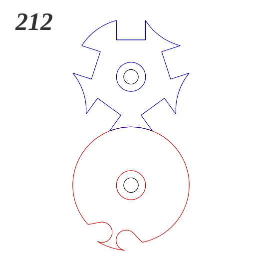
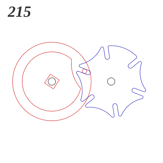
Similar ideas from 507 Mechanical Movements (click to see animation):
Driven Shaft
- Create a new part.
- Set units to millimeters (bottom right corner of window).
- Make an Extruded Base on the Top plane.
- Draw a circle centered on the origin and dimension it to 100 mm.
- Extrude to a depth of 10 mm.
- Color it yellow.
- Make a new Extruded Base on the top of the cylinder.
- Draw a circle centered on the origin, dimension it to 75 mm diameter.
- Extrude to a depth of 7 mm.
- Color it gray.
- Make a new Extruded Base on the top of the yellow cylinder.
- Add a horizontal constrution line from the origin to the right.
- Sketch a 7 mm diameter circle at the tip of the construction line.
- Dimension the construction line length to 43.75 mm.
- Exit the sketch.
- Set the extrusion direction 1 to "Up to Surface" and select the top surface of the gray cylinder.
This gives a little cylindrical peg.
- Color the peg you created green.
- Create a Circular Pattern feature.
- Set "Features to Pattern" to the green peg.
- Set the direction 1 to the edge of the gray cylinder and the number of copies to 8. Turn on equal spacing.
- Click OK to complete the pattern.
- Start a new Extruded base on the top of the gray cylinder.
- Add a horizontal construction line form the origin to the edge of the gray clinder.
- Add a second, diagonal onstruction line about 30 mm long from the origin up and to the right.
- Dimension the angle between the two construction lines to 18 degrees.
- Dimension the length of the diagonal construction line to 32 mm.
- Draw a circle at the end of the diagonal construction line and dimension it to 4 mm diameter.
- Set the extrusion depth to 3 mm.
- Color this new peg blue.
- Create a Circular Pattern feature to make 8 copies of this peg.
- Chamfer the top edge of the gray cylinder with a distance of 2 mm and a 45 degree angle.
- Fillet the top edge of the yellow cylinder with a radius of 2 mm.
- Color the chamfer and fillet features to match their respective cylinders.
- Save the part as DrivenShaft.SLDPRT.
- Make a new Extruded Base on the bottom of the yellow cylinder.
- Sketch a circle centered on the origin and dimension it to 15 mm diameter.
- Set the extrusion direction 1 to Mid Plane and the depth to 40 mm, so it will extend 20 mm in each direction.
- Click OK to finish the extrusion.
- Color the new cylinder orange.
- Save the part.
Driving Shaft
- Start a new part.
- Set units to millimeters (bottom right corner of window).
- Make an Extruded Base on the Top plane.
- Draw a circle centered on the origin and dimension it to 55 mm diameter.
- Extrude to a depth of 7 mm.
- Color the cylinder green.
- Start a new Extruded Base on the top of the cylinder.
- Draw a circle centered on the origin and dimension is to 12 mm diameter.
- Draw a horizontal line from the bottom point of the circle, extending to the left.
- Dimension the line length to 40 mm.
- Draw a spline from the edge of the inner circle (in the top left
quadrant), through one intermediate point, to the left edge of the line.
- Dimension the intermediate point so that it is 25 mm to the left of
the origin and 2 mm below the origin.
- Use Trim Entities to trim away one segment of the circle so it is
continuous with the "handle" formed by the spline curve and horizontal
line.
- Use the control point at the circle to bend the spline into a handle shape.
- Dimension the length of the control point arrow to 28.73.
- Dimension the horizontal distance between the control point and the origin to 5 mm.
- Extrude the handle to a depth of 3 mm.
- Color the handle blue.
- Fillet the tip of the handle to 0.5 mm and color it to match the handle.
- Make a new Extruded Base on top of the handle.
- Sketch a circle centered on the origin and dimension it to 7 mm diameter.
- Extrude to a depth of 3 mm above and 40.2 mm below.
- Color the cylinder orange.
- Start an Extruded Cut on the top surface of the green cylinder.
- Click on the edge of the green circle and do Convert Entities to import that circle.
- Draw a diagonal construction line from the origin up and to the left, contacting the edge of the cylinder.
- Add a horizontal construction line from the origin running to the left.
- Dimension the angle between the two construction lines to 22.5 degrees.
- Draw a circle centered somewhere on the diagonal construction line.
- Add a construction line from a point on the circle in the top right quadrant, through the midpoint,
to the opposite point on the bottom left quadrant.
- Add a Perpendicular relation between this construction line and the
diagonal line.
- Use Trim Entities to trim away the two quarters of the circle farthest
from the origin.
- Draw lines from the endpoint of each short construction line (which is coincident with an endpoint of the remainig arc) up and to the left, terminating at the edge of the green cylinder.
- Make these lines Parallel to the construction line on which the
circle was drawn.
- Use Trim Entities to trim away the portion of the green cylinder perimeter that lies outside the slot we're making.
- Dimension the slot arc to radius 4 mm.
- Dimension the distance between the origin and the center of the slot arc to 15 mm.
- Set the extruded cut to Through All and complete it.
- Fillet the lips of the slot with a 1 mm radius.
- Fillet the top edge of the green cylinder with the same 1 mm radius.
- Color the Extruded Cut and the two Fillet features green.
- Save the part as DrivingShaft.SLDPRT.
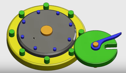
Assembly
- Start a new assembly.
- Insert both parts.
- Make both parts Float.
- Mate the bottom of the yellow cylinder's orange shaft to the Top Plane.
- Add a coincident mate between the bottom faces of the two orange shafts.
- Switch to an overhead view.
- Move the green cylinder close to the gray one.
- Add tangent mates between the edge of the green cylinder and two green pegs.
- Start a new sketch on the Top Plane.
- Select the bottom edges of the two orange shafts and click Convert Entities.
- Add Concentric mates betwen the two orange cylinders and their respective circles in the sketch.
- Hide the sketch.
- Now that the green cylinder is positioned properly, delete both tangent mates. DO NOT ROTATE THE CYLINDERS!
- Save the assembly as Intermittent.SLDASM.
Motion Study
- Go to SolidWorks Add-Ins and turn on Motion.
- Change the motion study type from Animation to Motion Analysis.
- Drage the black diamond to set the study duration to 16 seconds.
- Add a Motor driving the green cylinder at 20 rpm.
- Add a Solid Body Contact between the two parts.
- Click Calculate and observe the results.
Questions
- Why do we have both blue and green pegs? What role does each one play?
- You can adjust the playback speed to slow down the simulation and observe the roles more clearly.
- Does the shape of the blue handle matter?
- What would happen if we ran the motor in the opposite direction?
- Edit the motor feature and click on the Reverse Direction button to see.
More on Mechanisms
Dave Touretzky
Last modified: Wed Feb 1 05:16:22 EST 2017