Scribe Notes
Systolic Computing February 2, 1998

By Edward Brekelbaum
Reconfigurable Computing Seminar 2/2/98

Slide 1 Slide 1: Systolic Computing February 2, 1998


Slide 2 Slide 2: Talks


Slide 3 Slide 3: Lab 2


Slide 4 Slide 4: PipeRench Tutorial


Slide 5 Slide 5: Systolic Computing
Systolic computing was described by H.T. Kung in the late 1970's (the beginnings of VLSI design; before the 'RISC revolution').

Slide 6 Slide 6: Systolic Computing


Slide 7 Slide 7: Motivation
VLSI was a new technology, Kung wanted to try to reduce possible complications (which translate into design time, and therefore cost). At this time, microprocessors had few registers and no on-chip cache memory. A typical program could easily access memory as often as every other instruction, limiting performance to I/O rate. Applications which are dominated by IO will not benefit from a systolic implementation. The large degree of pipelining requires an equal degree of concurrency (and a systolic machine can more easily make use of it).

Slide 8 Slide 8: Using VLSI Effectively
Busses and other large fanout wires increase the capacitance, and thereby the delay.

Slide 9 Slide 9: Regular Interconnect
The 1-d and 2-d arrays are fairly straightforward, and tree network implementations have been done, but the hexangonal array is very different and little seen. It is an excellent structure for two operand, 1 result stream computations.

Slide 10 Slide 10: Eliminating the VN Bottleneck
Cache and registers offset the problem to some degree, but there is still the difficulty in address translation and access ports.

Slide 11 Slide 11: Balancing I/O and Compute
The instruction stream is also a bandwidth requirement; a fixed function machine has no instruction stream (maybe a few tag/control bits). However, this balancing requirement limits us to those applications which tolerate large degrees of pipelining.

Slide 12 Slide 12: Exploiting Concurrency
SIMD, MIMD, and Vector designs all require large busses which do not scale well. The design space is somewhat limited, but the vector/SIMD arena is clearly important, as all major microprocessors now include SIMD style instructions to speed certain applications.

Slide 13 Slide 13: Systolic Architectural Model
The algorithms for which systolic methods and reconfigurable computing can be applied are the same.

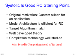
Slide 14 Slide 14: Systolic Is Good RC Starting Point.
Perhaps VLSI of the time lacked the density for a good FPGA implementation, or perhaps the circumstances were not right for the idea to be invented.

Slide 15 Slide 15: One Big Difference
A reconfigurable PE can be adjusted to the bit width of the application, and can make use of constant multiplication (and conversion of multiplication and division into shifts). General purpose PE's cannot take advantage of these optimizations.

Slide 16 Slide 16: Mapping Approach
A demonstration of the transformations presented in the Lam and Mostow paper to an algorithm in the Kung paper.

Slide 17 Slide 17: Various Possible Implementations
Broadcast and Fan-In are ignored due to their lack of scale.

Slide 18 Slide 18: Bag of Tricks
A summary of transformations available.

Slide 19 Slide 19: Bogus Attempt at Systolic FIR
The danger here is that the amount of hardware required is proportional to n, which could easily be infinite. The choice of 'in parallel' and 'in place' is very important. In this case, the outer loop forms a control on the output, while the inner loop works on the data. Control loops are best done as 'in place' while data loops should be 'in parallel'.

Slide 20 Slide 20: Bogus Attempt: Outer Loop
The outer loop was chosen to be 'in parallel', giving us a transformation of one PE for each output. We then see that Wj is replicated, allowing a transformation to broadcast the signal.

Slide 21 Slide 21: Bogus Attempt: Outer Loop-2
The retime transformation allows us two options, feeding data from the right and starting the X stream from Xn+k or from the left, as seen in the next slide. This choice affects the implementation of the driver circuit.

Slide 22 Slide 22: Bogus Attempt: Outer Loop-2a
This slide shows the structure for X fed from the left, starting with Xj-1.

Slide 23 Slide 23: Bogus Attempt: Outer Loop-3
The transformation in this slide was motivated by the realization that the X's form horizontal rows of identical inputs to the PE's. We finish the transformations here, to try a more achievable example.

Slide 24 Slide 24: Attempt at Systolic FIR
Notice that the algorithm is the same, except that the 'in parallel' and 'in place' have been switched. There are three transformations shown here. The first is the allocation of the inner loop body. The second uses the 'in parallel' hint to replicate the body to K PE's, allowing for feedback to maintain the dependency in Yi. The feedback is then eliminated by the use of internal registers on the Y stream.

Slide 25 Slide 25: Outer Loop
The outer loop is 'in place' allowing us to replace Xi and Yi with the X and Y streams.

Slide 26 Slide 26: Optimize Outer Loop Preload-repeated Value
The W stream is constant, so the value is loaded once and stored. This must be handled by the driver.

Slide 27 Slide 27: Optimize Outer Loop Broadcast Common Value
The X stream is the same across all the PE's, allowing the transformation to a broadcast line.

Slide 28 Slide 28: Optimize Outer Loop Retime to Eliminate Broadcast
Broadcast lines can be transformed to a retimed stream through the use of extra registers in each PE.

Slide 29 Slide 29: How It Works
At each stage, y is delayed one cycle to allow one additional x*w calculation to take place. The outgoing y is added to the new product to result in a total of k products and sums being completed by the final stage.

Slide 30 Slide 30: FIR details
The yellow boxes represent registers, and include the normal pipeline registers.

Slide 31 Slide 31: FIR details
It is interesting to note here that the multiply can be further pipelined to any degree without requiring additional registers after the add stage. This works in general, as long as the differences between the delays of all paths are kept the same.

Slide 32 Slide 32: FIR Summary
The 3K+1 figure should be 2K+1 (as the text implies), this comes from- K times: Load W, Load X, then Store Y. The systolic machine does a Load X, then a Load Y (the W's are loaded at configuration time). A final note on this new method, the multipliers are all constant multipliers (assuming the w's are known at initialization time). This could provide a significant win over general purpose multipliers. This example is optimal in that the throughput is O(1), at the cost of O(k) hardware and latency between input and output.

The class discussion included implementation of a hexagonal routing structure (rows of squares offset by one half of a side in relation to the rows above and below), and improvements in FPGA compilers (away from simulated annealing to a more algorithmic approach- a limiting of the potential design space to decrease compiler complexity).

Scribed by Edward Brekelbaum