Lead TAs: Cheng Dan (danc@andrew.cmu.edu), Shucheng Chao (shuchenc@andrew.cmu.edu)
Demo Date: Tuesday, April 19th, 2016
Challenge Statement:
Build a 2 link RR robot arm and demonstrate inverse kinematics
and path planing.
The Arm
Your robotic arm must adhere to the following criteria:
- The first link should have a length of 3.75 inches
- The second link should have a length of 2.5 inches
- The first joint should be able to rotate 180 degrees in a single direction
- The second joint should be able to rotate 180 degrees in both directions
Additionally, the following are highly recommended:
- The arm should have a stable base that doesn't slide around during the demo
- Please attach something to the end effector (e.g. a stick, a pen, a laser pointer) so we can make measurements
 |
|
Top down view of the arm
|
Demo: Path Planning
-
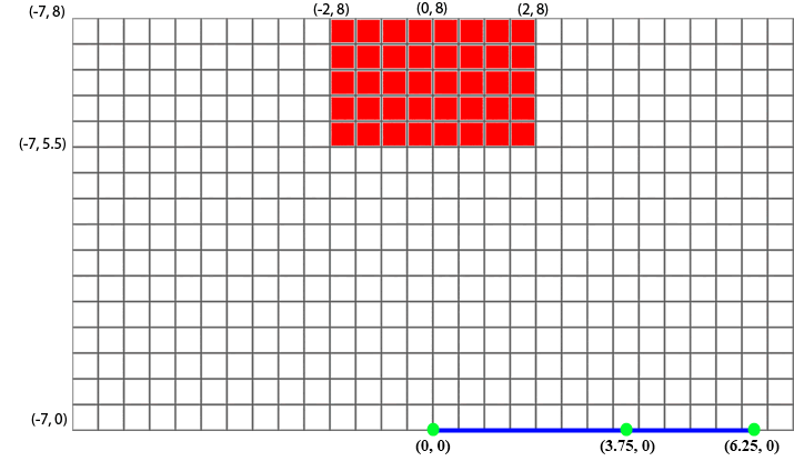
Using the arm you just built, perform the following tasks while avoiding the obstacle shown in the map below. Your robot arm must remain within the given grid (except when resting at the reference configuration). You will be given two positions on the map, call them A and B.
- Start by placing the arm in the reference configuration.
- Move from the reference configuration to position A and wait for user input (for example, a button press).
- Move from position A to position B and wait for user input.
- Go back to position A and stop there.
- Your try immediately ends if the robot ever touches the obstacle or leaves the grid.
- Three tries will be given in order to improve your score if needed. All tries are independent of each other. An easier option of running the trial without an obstacle can be requested with a penalty of 30 points.
Map:
 |
|
Map in cartesian space. Red
indicates an obstacle, Blue represents the arm in its
reference configuration.
All numbers are in inches. |
How to:
Note that the way point based planner is only suggested. Feel free to implement any other planner to solve this task.
- Start by writing a function that will perform inverse kinematic calculations. Such a function would probably take a desired 2D position and return a set of joint angles.
- Write a function that given the current configuration and desired configuration, moves the joints such that the robot ends up in the desired configuration. This can be done by setting the desired encoder value and spinning the motors in the correct direction.
- Convert the obstacle into c-space. You can do this analytically, or by testing your arm at small degree increments.
- Add a path planner to handle the obstacle. We recommend your planner from lab 5.
- Use that inverse kinematics function to get good C-Space angles for the given start and end positions.
- Run the planner using these positions to reach the goal position. Make sure the planner is working on C-Space angles and not X-Y positions.
Also note that your planner must be intelligent and efficient. In other words, it is not acceptable to simply fold the second link untop of the first one everytime you move between points.
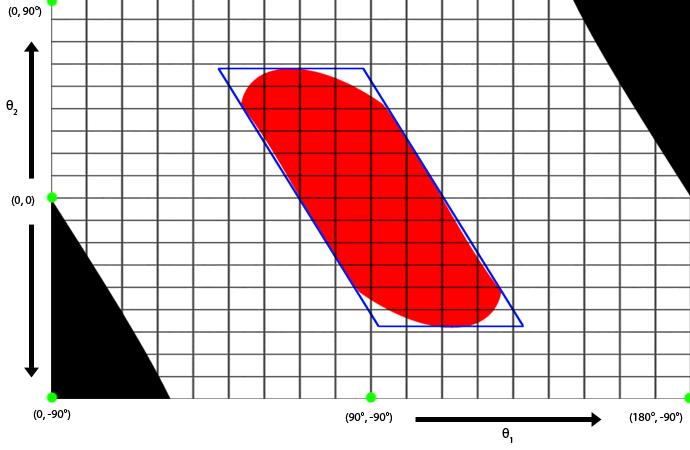
C-Space Map Example:
 |
|
A representation of the cartesian
map with the obstacle in the robot's configuration
space.
Note that your map may look different. Red : Obstacle Blue : Approximation of the obstacle as a parallelogram Black : Outside the map. |
Other tips:
- The encoders are accurate only up to 1 degree. So make sure you round off the value to the closest degree before setting the desired encoder counts.
- If you roll your own atan2 function, watch out for all of the special cases.
- Make your robot as rigid as possible.
Demo Evaluation:
Error will be calculated using the L2 distance metric.
You will be given 2 positions, A and B. These will be at least 1/2 inch away from the obstacle.
- The path your robot should take is: Reference --> A --> B --> A
- Credit is dependent on how close your end effector is to the given positions. Make sure you specify before your run what point on your arm you would like us to measure from. For the complete breakdown and more details, see the grading sheet.
- Touching the obstacle ends your current try. Positions reached before contact will still count towards your score for that try.
- Your arm should come to a complete stop at each position, and
should not continue until your grader is finished measuring and
recording that point.
World Map (NOTE: 11x17 paper) : World Map
Grading: (100 points)
Points for the lab will be assigned based on your software functionality, as determined by hardware trials, as well as your analysis.
- Robot Performance (65 points)
- Robot finishes within (.25in, .50in) of Postion A - (10, 5) points
- Robot finishes within (.25in, .50in) of Postion B - (25, 10) points
- Robot finishes within (.25in, .50in) of Postion A - (30, 20) points
- Analysis (35 points)
- Briefly explain your path planning algorithm and provide any diagrams necessary to clarify it. (10 points)
- If given more time, what improvements could you have made to your software design? What about your robot arm design? (10 points)
- Show the TA a diagram of your robot's configuration space. Please be sure to label axis and dimensions. (10 points)
- How would your planner be affected if a third arm was added? What changes would be necessary to make the robot run efficiently? (5 points)
Keywords : ArcTan2, Inverse Kinematics
Last updated 04/10/2016 by Shucheng Chao
(c) 1999-2016: Howie Choset, Carnegie Mellon
