SolidWorks Intro Part 3
Dave Touretzky
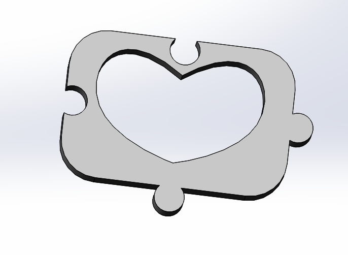
HEART PUZZLE PIECES:

- Start a new part.
- Create an Extruded Base on the front plane.
- Sketch a rectangle extending from the origin.
- Dimension the rectangle to be 1 inch high and 1.5 inches wide.
- Add a vertical centerline through the midpoints.
- Add a horizontal centerline as well.
Making curves
- Select the curve tool
- Start a curve by clicking somewhere in the left half of the rectangle, near the top.
- Put the second point below and to the left of the first one; double click to end the curve, or hit escape to exit the curve tool.
- If not selected, click on the curve to select it.
- Play with the control points:
- The diamond changes the angle of the curve but not the length.
- The arrowhead changes the length but not the angle.
- The dot changes both length and angle.
- Snap the two endpoints to the vertical centerline.
- Adjust the control points to make half a heart shape.
- Click on the Mirror Entities tool and mirror the curve to make a heart.
Making puzzle connectors with trim
- Draw a small circle centered slightly outside the right edge of the rectangle, centered on the edge midpoint.
- To do this, select the circle tool, put the mouse on the right edge (which makes the midpoint visible)
- Slide it up until you reach the midpoint, then move slightly to the right.
- Draw a horizontal centerline connecting the circle to the right edge.
- Dimension the circle diameter to 0.2 inches (radius 0.1 inches).
- Dimension the centerline to 0.07 inches.
- Draw another small circle centered slightly INSIDE the left edge of the rectangle, on its midpoint.
- Select the circle, then shift-click to select the other circle.
- Add an Equal relation between the two circles.
- Draw a horizontal centerline connecting the new circle to the left edge.
- Note: this will overlap the existing mid-point centerline.
- Click on the centerline, then right click and do "Select Other" to get the short one.
- Shift-click on the other horizontal centerline.
- Add an Equal relation between the two centerlines.
- Notice that the sketch contains crossed lines (intersecting contours).
- Click on Exit Sketch and you'll get an error because of intersecting contours.
- Go back in and edit the sketch.
- Click on the Trim Entities tool.
- Click and drag across the line segments you want to delete, so no lines cross.
- Use control-Z to undo if you make a mistake.
- Click on Exit Sketch and set the extrusion depth to 1/8 inch.
- Now you have a puzzle piece
- Edit the sketch again.
- Change the arc radius to 0.3 inches.
- Notice that both arcs changed at once.
- Then change the arc radius back to 0.1 inches.
- Notice that the centerline endpoints are no longer aligned with the edge.
- Click on a centerline endpoint, then shift-click on the edge.
- Add a Coincident relation between them.
- Do the same for the other centerline endpoint.
- Now try resizing the arcs and note that the endpoints stay fixed.
- Repeat the same process to add top and bottom connectors to the puzzle piece.
- Add a 0.25 inch radius fillet to the corners of the piece.
- Save your file as HeartTile.SLDPRT
Assembly of Pieces

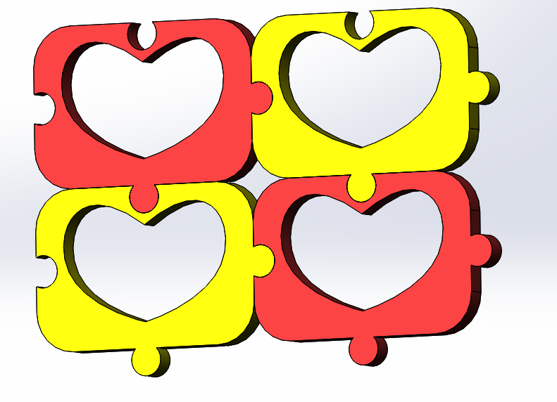
- Make a new assembly and insert four heart tiles.
- Color two of them red and two yellow.
- Mate them together as if they were puzzle pieces.
- Save your assembly as HeartMosaic.SLDPRT
THE HOLE WIZARD
Three ways to make a hole:
- Closed contour in a sketch to be extruded.
- Extruded cut.
- The Hole Wizard:
Why you should use the hole wizard:
- Correct sizing for standard fasteners (ANSI or metric).
- Adjustable fit tolerances.
- Proper symbology for machinist drawings.
Hole Wizard Example:
- Start with your HeartPiece part.
- Click on Hole Wizard in the Features tab.
- Click on "Hole" (third entry in the grid of hole types).
- Select "ANSI inch".
- Select "Screw clearance".
- Change the clearance type from "Normal" to "Close".
- Click on the "Positions" tab at the top of the dialog box.
- Click on the face of the part.
- Notice the mouse pointer changes to a point tool. Click to place a point, indicating a hole location.
- Click again to place another point.
- Click on the green checkmark to complete the hole dialog.
- To edit whole positions, open the "Clearance Hole" feature in the Feature Manager tree and
edit the first sketch, which specifies the hole positions.
- The second sketch describes the shape of the hole; don't edit that.
|

