First, the Modeling Subsystem intends to create a model of the airplane as well as methods for virtually navigating the airplane and its components. The methods provided will be used by the Augmented Reality Subsystem, which is responsible for providing location information of the airplane with respect to the mobile mechanic performing the maintenance. The methods provided by the Modeling Subsystem will map location information in terms of (x,y,z) coordinates. Second, for inspection and repair of the aircraft, the Modeling Subsystem will provide methods to place, remove, review, and modify the "Stickies" in a Sticky database owned by the Workflow Subsystem. Third, the subsystem will create, using Java 3D, a web-based navigation for the virtual airplane that allows for remote users to view and manipulate the aircraft. Fourth, the Modeling Subsystem will interface with the Authoring Subsystem to provide them with the same methods mentioned above and provided to the Augmented Reality Subsystem, in order to manipulate the airplane and its components, which will be used in creating the IETMs by the Authoring Subsystem.
Currently, there is no automated system performing the actions that the Modeling Subsystem will perform. The client uses paper documentation to do all inspection and repair workorders. IETMs including text and wireframes views will replace paper text and blueprints. The Modeling Subsystem, in particular, will streamline and replace the paper blueprints and pictures by allowing for a virtual representation of the airplane and its components.
At the core of the Modeling Subsystem is the model itself, in this case an F/A-18. Internally this model will be represented in two ways: a CAD model of the aircraft which can be used for creating graphical views, and a hierarchical parts catalog for correlating sticky notes and workorders with specific components. At the top of this hierarchy is the entire plane; descending one level might leave you at the fuselage, left wing, or cockpit, for example; and descending further from there would leave you at another sub-component.
Surrounding the aircraft model are various additional features, which will be defined in subsequent sections. These include, for example, web-based navigation tools and a graphical interface for dealing with stickies, the airplane, and its components.
The model subsystem has the following functional requirements:
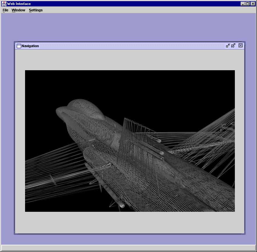
The Modeling Subsystem will mainly interact with other subsystems. There will be situations where the subsystem will need to provide a web-based user interface for users who are not directly interacting with the airplane to review its status and interact with sticky notes. The user interface will lie on top of the methods we provide for other subsystems, so it will serve to manipulate stickies or navigate through the airplane and its components. For example, an officer might want to quickly check the availability of an aircraft without having to go down to the hangar and put on a wearable computer. The officer might also wish to review stickies on the airplane or look at a look at a specific aircraft components with all the stickies located on it. The officer could also obtain rotated views of the aircraft or separate components. This tool should be intuitive to use. Its main purpose will be to easily navigate through an aircraft without having to go to the aircraft's location. To protect the system from human errors, only authorized users will be allowed to use the system. The users will only have read access to database information, and will not be allowed to make changes, but only to view/navigate through the already existing aircraft and corresponding data.
The user interface will interact with the user through a toolbar and it will be generated via Java applet. It will be easy to use and will not require any particular training.
First, documentation will be provided to describe the features and operation of the web-based navigation tool. Help pages will be included. Domos of the interface will also be included. Second, documentation will be provided for all the methods provided by the Modeling Subsystem and used by other subsystems. The documentations will be included in the implementation and will also be generated via Javadoc. Additional documentation on the methods will be provided to produce an overall view of the functionality of our subsystem and to explain this functionality to other subsystems. Having said this, it is clear that our documentation will mainly be used by other subsystems and will provide an extensive description of the methods, dealing with navigation of airplane/components and manipulation of stickies, available to other subsystems.
The system design document (SDD) and object design document (ODD) will provide future maintainers of the STARS system with the details of the model subsystem's internal implementation. The SDD will also detail the API for the model subsystem.
The Modeling Subsystem will implement the web-based graphics API with Java 3D. It will be web-based, which introduces the issue of web availability on the computer used. A more important requirement is memory space available on the device when navigating through a wireframe model or manipulating stickies. Each wireframe object (the graphical representation of the physical airplane) is an enormous collection of points, detailing the shape of the physical airplane. A hierarchical database of wireframe objects will exist including the components and the level of decomposition per component. These wireframe objects will be large, so storage space for these objects will be necessary. Sticky information will also need to be stored, including sticky GUI, description, location, and any additional information. The portable devices will need to have enough storage space to accommodate these issues. We do not have exact estimates of how much storage the system will need because we lack concrete information, which we will accumulate as we develop a prototype of the system. But of the sake of providing a number, we give 1Gigabytes of RAM as an upper limit of memory storage.
Near-realtime or realtime data is needed for Augmented Reality and Authoring to build their interface for the aircraft maintainers or the IETMs, respectively. Workflow will also need input from our subsystem, in order to update their sticky database, but this process does not need to be realtime. After numerous considerations, we concluded that Java 3D will be used by the Modeling Subsystem to build the API. Here are the reasons:
Since the Modeling Subsystem mostly interacts with other subsystems (AR, Authoring, Workflow, Inspection, Repair), error handling will be done through method calls between subsystems, meaning our subsystem will inform the user subsystem that a problem has occurred. The other subsystem will then have to correct the problem by trying to call our methods with the correct parameters. For example, an error will occur if another subsystem passes us the wrong coordinate parameters for a sticky or airplane component. In this case we need to inform them of their error by returning an error message, which is descriptive of the problem. The other subsystem will then try again with different parameters. Other input errors could occur when:
The Modeling Subsystem needs to provide direct error handling for the web-base user interface. In this case, the subsystem will interact with a user and needs to provide its own descriptive popup to notify the user of the problem.
Extreme conditions could occur when the system is overloaded or it takes up a large amount of memory space. This could occur if multiple subsystems are trying to use our subsystem at the same time, or a single subsystem is performing complex wireframe generations, or both. In both cases, our system will be slowed down, because of the multiple processes it needs to perform. In the case of a complex wireframe generation or multiple wireframe generation occurring on the same CPU, our system might experience shortage of memory storage for the wireframes. As mentioned above, will provide a limit of memory storage needed and will ensure that it is met.
The Modeling Subsystem will be interfacing will all other subsystems in the project. Here is a description of each interaction:
The main issue we discuss here is the compromise of the system slowing down when there is an overload. An overload could occur when there a multiple subsystem using our subsystem at the same time or a subsystem is performing complex wireframe generation. One possible way to improve performance is to reduce the number of running tasks using some heuristic of which tasks to eliminate or delay. Another way is to simply inform the user subsystem of the memory or time inefficiency.
The Modeling Subsystem must recognize when other subsystems that it relies on are down. For example, the Repair Subsystem is currently interfacing with our subsystem and our subsystem must contact Workflow's database in order to gather information to satisfy Repair's needs. If Workflow's database is not currently up, our subsystem needs to carry over the appropriate message to Repair. Repair then could either continue with something else, or try again at a later time. This is a standard way to deal with this problem if a system relies on a central database that lives on a server. Another way to deal with the problem is to keep a copy of the database on the currently used computer. This will introduce update issues, but will solve the concurrency problem. The issue of updating the database is taken care by Workflow.
The Modeling Subsystem must be reliable, in the sense that it needs to provide accurate output provided given input. For example, the subsystem will have implemented various methods for navigating the airplane and its components. These methods must provide the correct results provided the given parameters passed to them. All views and rotations of component parts or stickies must be performed correctly.
The web-based user interface provided by the Modeling Subsystem must run on any hardware/OS which has Java 3D. Platform independence is greatly appreciated.
Since the Modeling Subsystem is closely related to all other subsystems, it is very likely it will need to be modified if another subsystem changes in the future. The implementation of our subsystem could change if the changes are needed for other subsystems to operate properly.
The subsystem could also be extended to something other than the F/A-18 aircraft. This subsystem needs to be modeled accordingly, creating a wireframe and component objects with relations for the new system. Since the subsystem plans to use the Abstract Factory Pattern, minimal other changes are anticipated.
Hardware/Software upgrades could influence our subsystem's web-based user interface. Changes have to be integrated appropriately.
The Modeling Subsystem will be interfacing with other subsystems by providing certain functionality. It will not, however, directly come in touch with the physical environment. The other subsystems will need to take into account physical environment, which is where they will normally operate.
The Modeling Subsystem will provide a web based user interface, which we envision to be run on a desk at some office away from the actual aircraft.
The Modeling Subsystem will reside on the same computer and will run concurrently with the subsystems it interfaces with. If shared memory is used for communication between the two processes of different subsystems, it may undermine the reliability of the whole system. This is because, if unauthorized personnel got access to one of the subsystems, it would be possible for him/her to access the other subsystems, for example, obtaining a copy of the F/A-18 model. The person then might give the model to the enemy. So, if shared memory is used for interaction between the subsystems, each subsystem must secure access to its functionality. For example, Inspection must secure creating of stickies, and Repair must secure removing of stickies. Workflow must provide secure access to its databases. Our subsystem will interface with other subsystems, so we rely on other subsystems and their solution of security issues with outside users. Also, since our subsystem will most likely reside on a wearable computer, the connection between the wearable computer and the workstation should be encrypted to avoid eavesdropping.
The Modeling subsystem will not hold any permanent data pertaining to the Workflow Subsystem. Data is copied from the workflow database to the wearable computer during startup syncing, and copied back to the workflow database after the job is finished. Therefore sticky information will not be stored by our subsystem, but will only travel through it, when communicating between Workflow and Inspection/Repair. Navigation information, however, which will be used by AR and Authoring, will need to be stored. This includes the aircraft design and graphical representation of its components. This data will be static and copies will be provided for instalation to subsystems that need it. The subsystem should be installed and maintained by a trained technician, who has extensive knowledge of the underlying system. Initially this job will be taken by one of the modeling team members, who will be responsible for the training.
Our subsystem must be implemented in a platform independent manner, which will be accomplished with a Java-based implementation of the subsystem. In this manner, a common database can be used for both the inspection (HMD) and web-based navigation tools. As a result of using Java, the amount of information we can display or handle at once may be limited. Java is not the fastest way to implement the system, so the representation of the plane may need to be scaled down if it is to be displayed in real-time.
Object and case models will be constructed using Together/J.
NavigateComponent:

Place Sticky
Remove Sticky:

Modify Sticky:

Review Sticky: