Making Gears
This is how to make a 40-tooth gear. The gear diameter will be
calculated automatically based on the constraints that we set. With
40 teeth, the tooth spacing will be 360o/40 =
9o. We'll start by drawing half a tooth, then mirroring
it to make a whole tooth, and then copying that feature 40 times.
- Start SolidWorks and begin a new part.
- Begin an Extruded Base feature on the Front Plane.
- Make a circle centered on the origin with a radius of around 1.75
inches (diameter 3.5 inches). Don't set a hard dimension. Make the
circle "for construction" (check the "For construction" box in the
property editor).
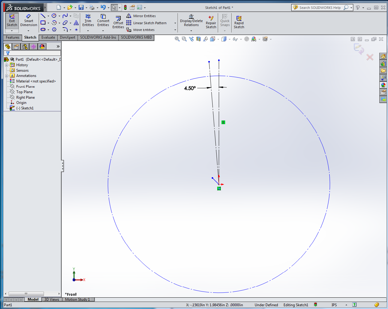
- Draw a roughly 2 inch vertical construction line from the origin
straight up. Make another roughly 2 inch construction line, also
emanating from the origin, but angled slightly to the left of the
vertical line. Then use the dimension tool to set the precise angle
between the two construction lines to half the inter-tooth angle, or
4.5o.
- Create a point where the vertical line intersects the circle.
- Draw a short horizontal line beginning somewhere on the vertical
line outside the circle, running to the left. Dimension the length of
this horizontal line to 0.017 inches. (Set the dimension to display
3 digits of precision instead of the default 2 digits.) Dimension the
distance between the right endpoint of the line and the point you made
on the circle, which should be directly below it, to 0.08 inches.
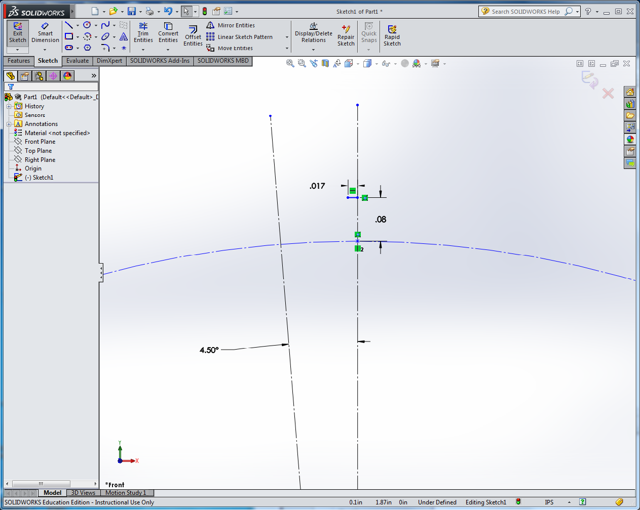
- Draw a new line beginning at the left endpoint of your horizontal
line and moving diagonally down to the left, terminating on the circle about
half-way between the two construction lines. Dimension the angle between
this line and the vertical construction line to 45o.

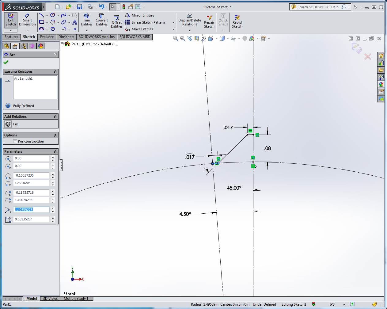
- Draw a centerpoint arc, centered on the origin (point 1). Point
2 should be the left edge of your 45o line. Point 3 should
be on the circle but well to the left of the left construction line.
The arc tool doesn't want to make really short arcs, so we'll draw the
arc longer than it needs to be, and afterwards move the left endpoint
to the correct position.
- Click and drag on the left endpoint of your arc and snap it to
the left construction line. Note: centerpoint arcs don't always snap
to the place you want them to. Instead they may create a spurious new
point that causes problems later, so always check the endpoints after
creating one of these arcs. To check an endpoint, click on it, wait
for the pop-up menu, then click on the "Select Other" icon. If you
see more than one Point in the pop-up list of objects, you will need
to merge the points. To do this, click on the first point in
the pop-up list. Then shift-click on the point itself (not the pop-up
list entry). This should leave you in the properties editor with two
points selected; click on the Merge relation to merge them. Check the
other endpoint of the arc as well.
- Dimension the arc length to 0.017 inches. Note: to dimension the
true arc length instead of the straight-line distance between the
endpoints, first click on each endpoint, then click on the arc itself.
You'll see a curved line appear above the dimension value. If you
can't get this to work, just dimension the linear distance between the
endpoints; that's close enough. Set the dimension display to three
digits of precision.
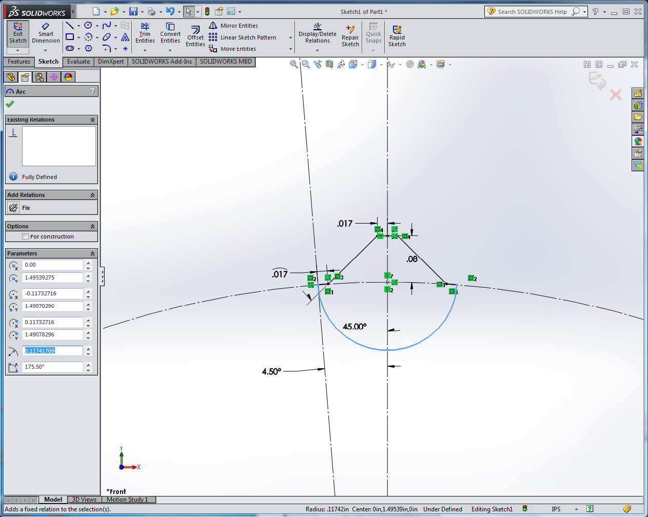
- All your lines should now be black (fully defined), and the display
should look like this (click on the image for a larger version):
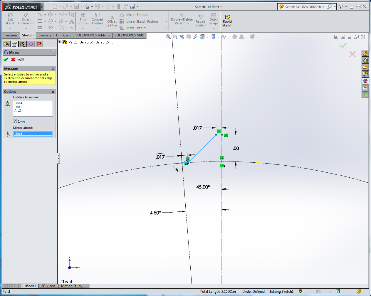
- Click on "Mirror Entities" and select the horizontal line, the
45o line, and the short arc as the entities to mirror.
Then select the vertical construction line as the line to mirror
about. Click on the green checkmark to complete the mirroring.
- We need to make a closed shape in order for the extrude to
succeed. So draw a centerpoint arc whose center is the point you
created on the vertical construction line, and whose endpoints are the
left and right edges of the respective arc segments. Remember to
check the arc endpoints and merge any duplicate point objects. The
display should now look like this:
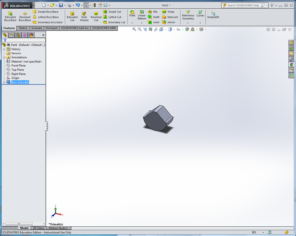
- Accept the sketch and set the boss-extrude depth to 1/8 in. You
should now have one gear tooth floating in space:
- Now we're going to make the body of the gear. Begin a new
Extruded Boss/Base feature, again sketching on the Front Plane. (You
will have to expand the Feature Manager tree in the top left corner of
the graphics window to reveal the Front Plane.)
- Make a circle centered on the origin with a radius of roughly
1 inch (diameter 2 inches).
- Select the circle, and then shift-click on the tiny little arc
edge at the left base of the gear tooth. This should leave you in the
properties editor with an arc and an edge selected.
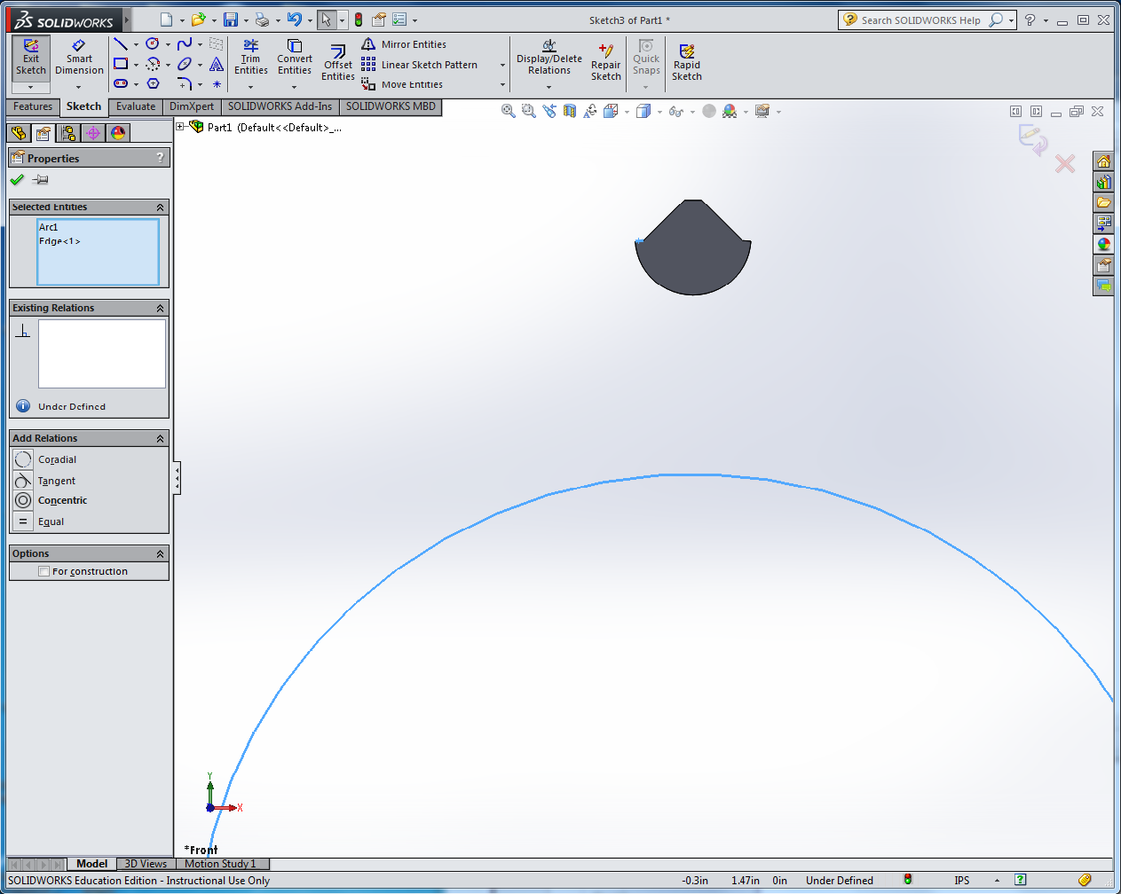
- Add a Tangent relation to make the circle coincide with the edge
segment.

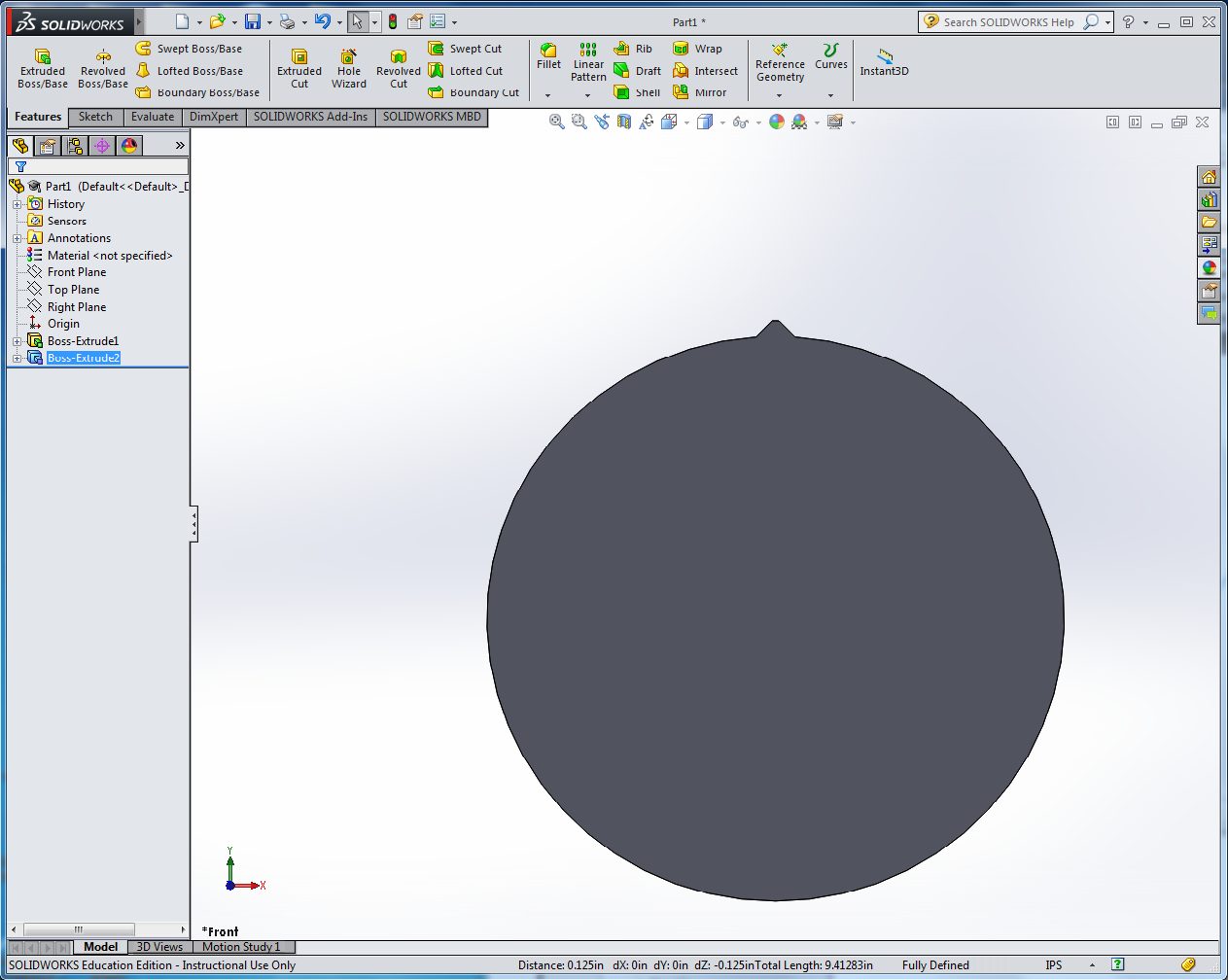
- Accept the sketch and set the boss-extrude depth to 1/8 in. Make
sure "Merge result" is checked in the extrude dialog box. You
should now have a disk with one tooth on it:
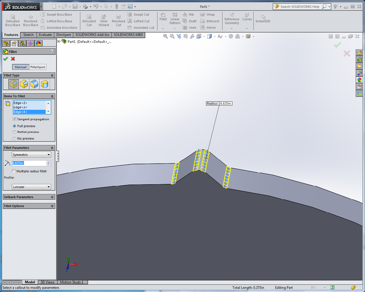
- On the Features tab, select Fillet and add a 0.025 inch (not the
default 0.1 inch) radius fillet to the four edges of the tooth:
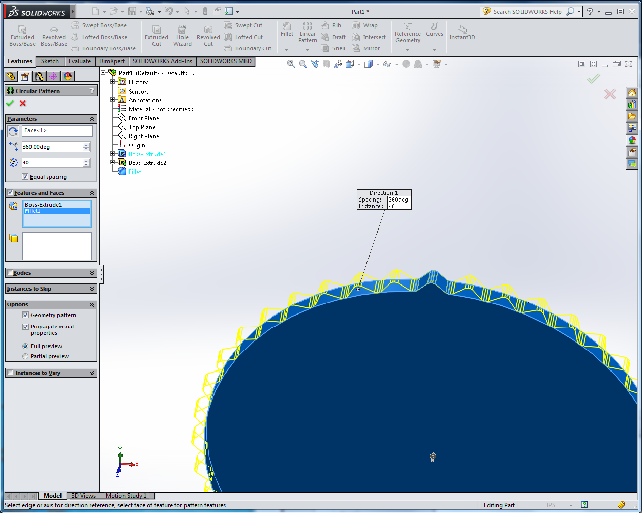
- On the Features tab, click on the Linear Pattern pulldown menu
and select Circular Pattern. Click in the Parameters box at the top
and select the circular edge face (not the flat front face) of
the disk. Check the Equal Spacing box, then set the number of copies
to 40. At the bottom under Options, check the "Geometry pattern" box.
In the Features and Faces box, select the first Boss-Extrude
and the Fillet feature. (You will need to open the Feature Manager
tree to select these features.) You should see a yellow outline of
the 40 teeth. Click on the green checkmark to accept the pattern.
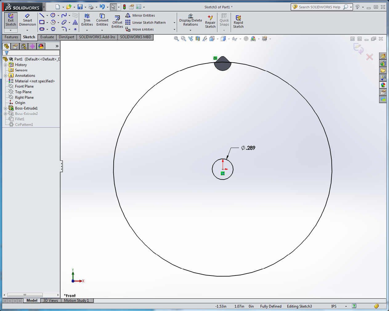
- For the gear to spin freely on the hexagonal shaft, we need to
make a hole in the center. The hexagon has a 1/4 inch diameter, but
that means the distance between opposite vertices is actually a bit
more than that. Edit the sketch for the second Boss-Extrude feature
and add a circular hole centered on the origin with a diameter of
0.289 inches. Exit the sketch.
THE HOLE WIZARD
Three ways to make a hole:
- Closed contour in a sketch to be extruded.
- Extruded cut.
- The Hole Wizard:
Why you should use the hole wizard:
- Correct sizing for standard fasteners (ANSI or metric).
- Adjustable fit tolerances (use close fit for laser cutters to compensate for kerf).
- Proper symbology for machinist drawings.
Hole Wizard Example:
- Click on Hole Wizard in the Features tab.
- Click on "Hole" (third entry in the grid of hole types).
- Under "Standard", select "ANSI inch".
- Under "Type", select "Screw clearances".
- Under "Size", select #4 size.
- Change the clearance type from "Normal" to "Close".
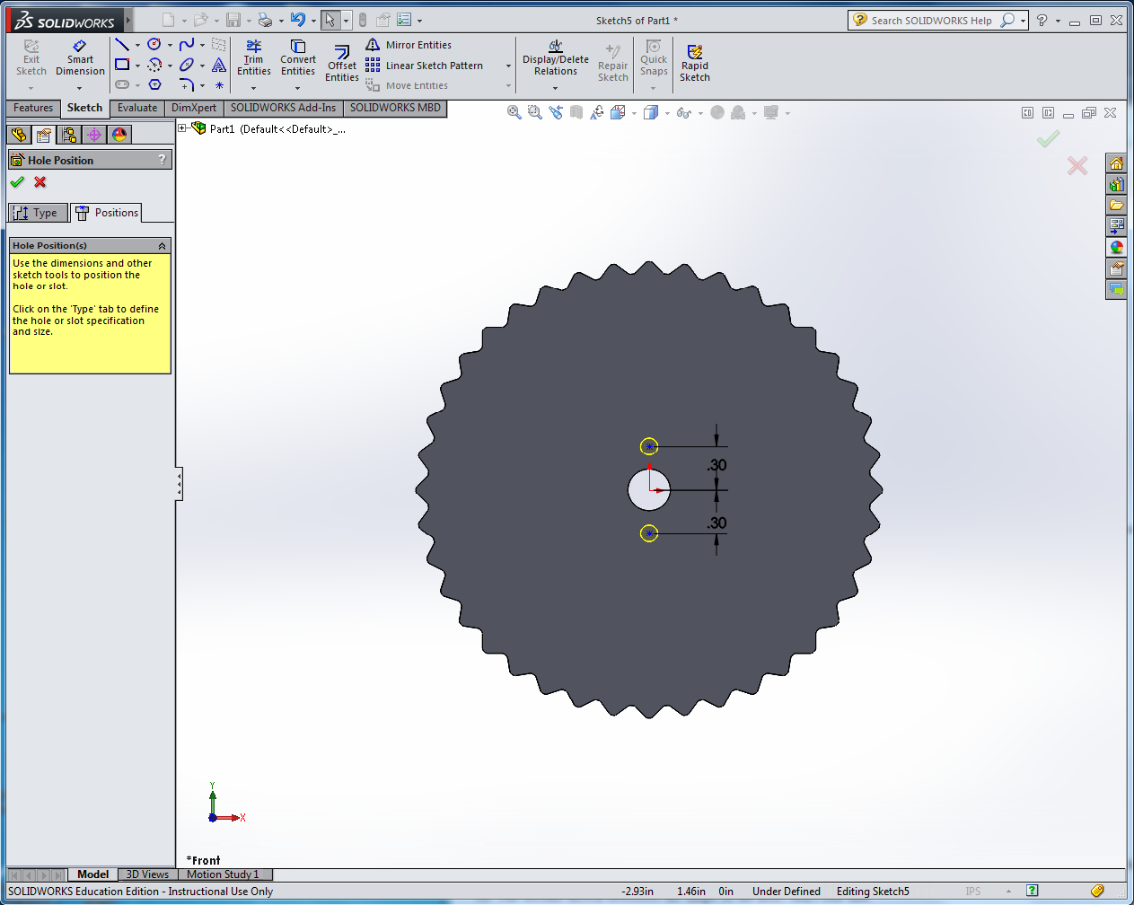
- Click on the "Positions" tab at the top of the dialog box.
- Click on the face of the part.
- Notice the mouse pointer changes to a point tool. Click to place a point
above the central hole and directly above the origin.
- Click again to place another point below the central hole and directly below the origin.
- Use the dimension tool to set the points 0.3 inches from the origin.
- Click on the green checkmark to complete the hole dialog.
- To edit whole positions, open the "Clearance Hole" feature in the Feature Manager tree and
edit the first sketch, which specifies the hole positions.
- The second sketch describes the shape of the hole; don't edit that.
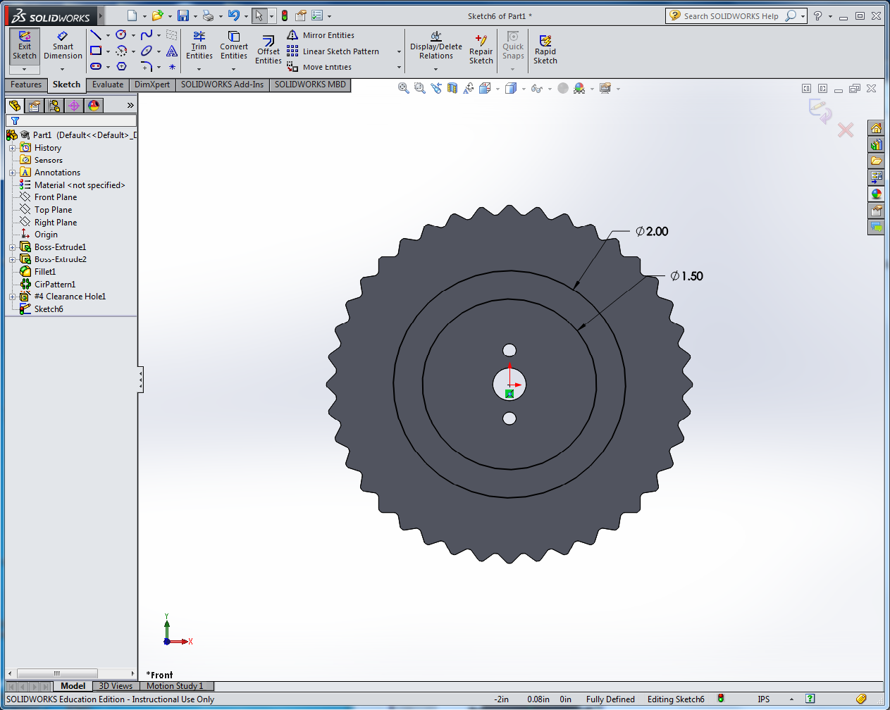
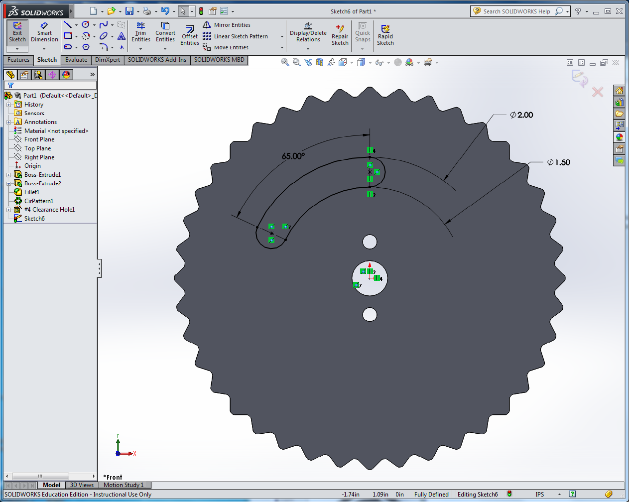
MAKE THE SLOTS
- Start an Extruded Cut feature on the face of the gear.
- Draw two concentric circles centered on the origin that lie
between the screw holes and the base of the teeth.
- Dimension the inner circle to diameter 1.5 inches and the outer
one to diameter 1.75 inches.
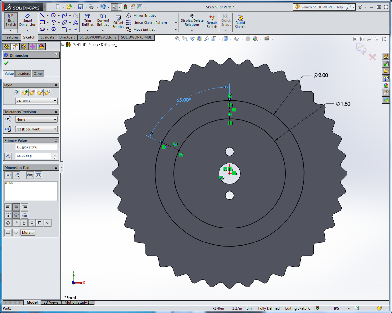
- Draw a construction line extending vertically from a point on the inner
circle directly above the origin to the corresponding point
on the outer circle.
- Draw a second construction line connecting the two circles roughly 65 degrees to the left of the first one.
- Dimension the construction lines to be 65 degrees apart.
- Draw a point at the midpoint of each construction line.
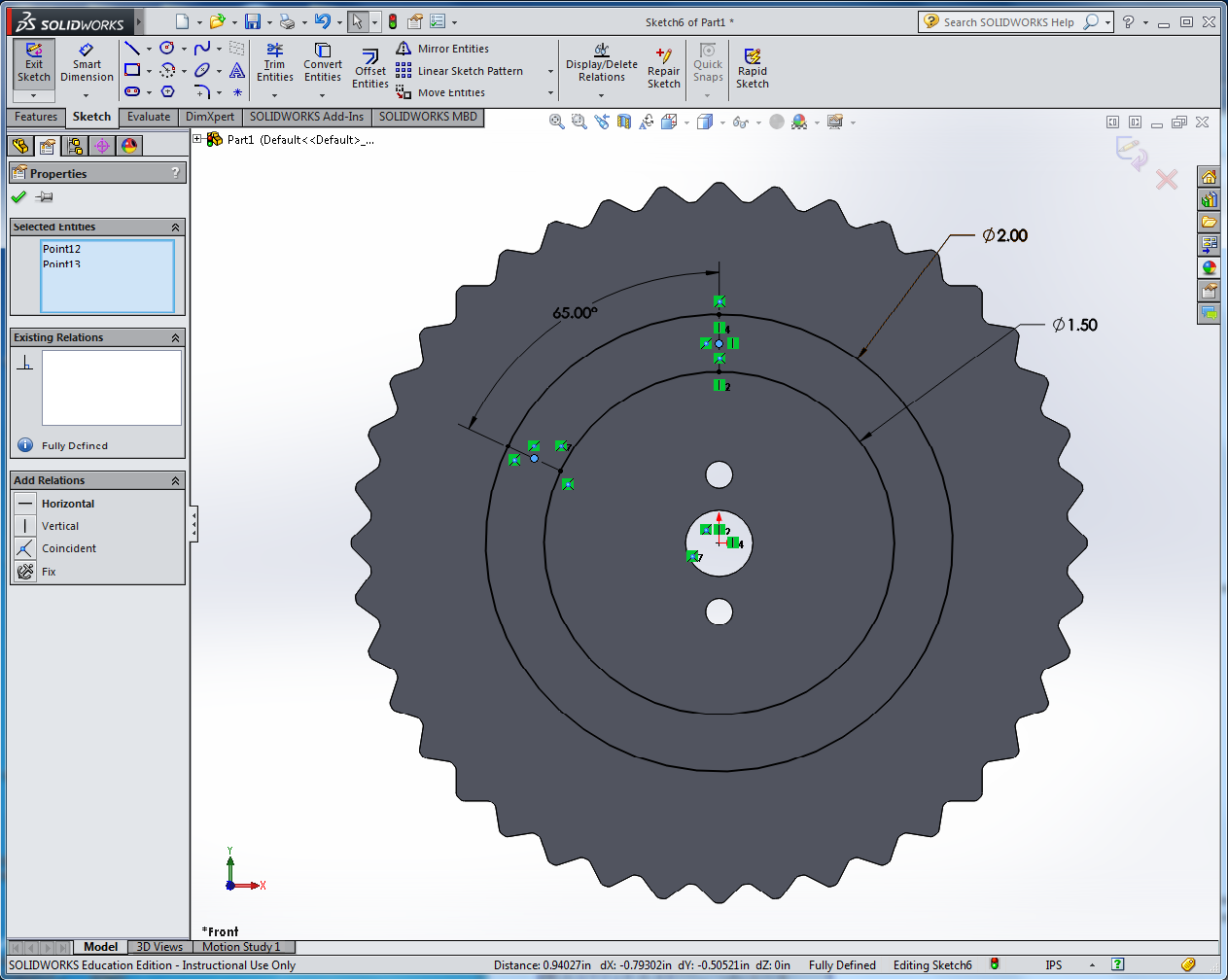
- Use the centerpoint arc tool to make the curved ends of the slot, using the midpoints of the
construction lines as the centerpoints.
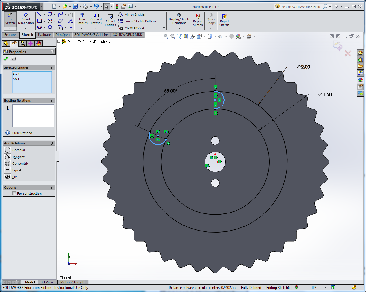
- Use the Trim Entities tool to delete the concentric circles
outside of the slot. Rirst, click on the Trim Entities tool (it looks
like a scissors). Next, click and drag the mouse across the two
concentric circles outside of the slot you're drawing. This
erases most of the circles, leaving just the slot. Use control-Z to
undo if you make a mistake.
- Click on the Linear Sketch Pattern pulldown menu and select Circular Sketch Pattern.
- To fill in the Parameters box, click on the four arcs that form the slot.
- Make sure the Equal Spacing box is checked, and set the number of repetitions to 4.
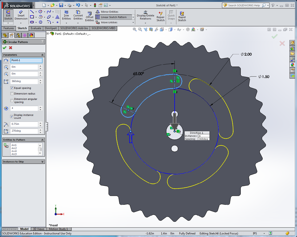
- Click on the green checkmark to accept the pattern.
- Click Exit Sketch.
- In the Extruded Cut dialog, if necessary, click inside each slot to add it to the list of Selected Contours.
- Set the cut direction to "Through All" and click on the green checkmark to complete the extruded cut.
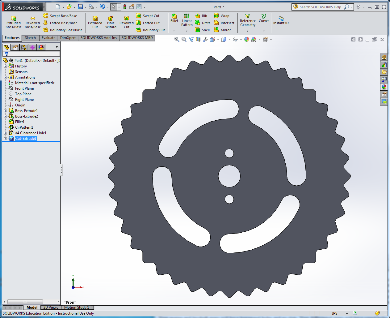
- Save your part as MyGear.SLDPRT.
Make Some More Gears
In this exercise you made a 40 tooth gear. In the Pocket Transmission
assignment you need gears with different numbers of teeth, and with
different spacing of the #4 screw holes. See the shop drawings for
details.
To make gears with different numbers of teeth, remember that the
inter-tooth angle is 360/N where N is the number of teeth; in your
sketch you will use half this angle for the construction line. You
can type the formula "360/40/2" directly into the dimension dialog
box. SolidWorks will automatically calculate the gear diameter based
on the sketch relations you've defined. You will also need to specify
the same value of N in the Circular Pattern feature. Note: sometimes
changing the number of repetitions in a Circular Pattern causes
rebuild errors. In that case, simply delete or suppress the feature
and make a new one.
|