16-299: Elegoo Tumbller balancing robot assembly.
Other unboxing and assembly videos:
Company instruction video: This is for an older version of
the robot than what we have (V1.0 vs. V1.1). However, I enjoyed the sound
track.
Unboxing
Assembly time lapse
Another assembly video
Unboxing in Japanese
Unboxing in Spanish
Unboxing in Spanish 2
Unboxing in Spanish 3
Unboxing in German?
Unboxing in Australian
Assembly in Italian?
Atkeson's Elegoo Tumbller balancing robot assembly.
This information is intended to augment the assembly tutorial/manual that
comes with the robot.

Unboxing.


The battery and controller board have been removed from the box.
The battery has been charged, and the controller board modified.
However, you should charge the battery again just to make sure it is charged.
Keep the parts in the little plastic bags until you need that part.
Especially the screws. Only take what you need for the current step
from the bags, or you will have a hard time figuring out which screw
is which.
Get your battery charging first thing.

A USB cable is included.

The charging port.

I don't know if the switch should be on or off while charging.
I put it to off.

The light is on or flashing (green) while charging, and goes off when fully charged.
A red light means the battery needs to be charged.
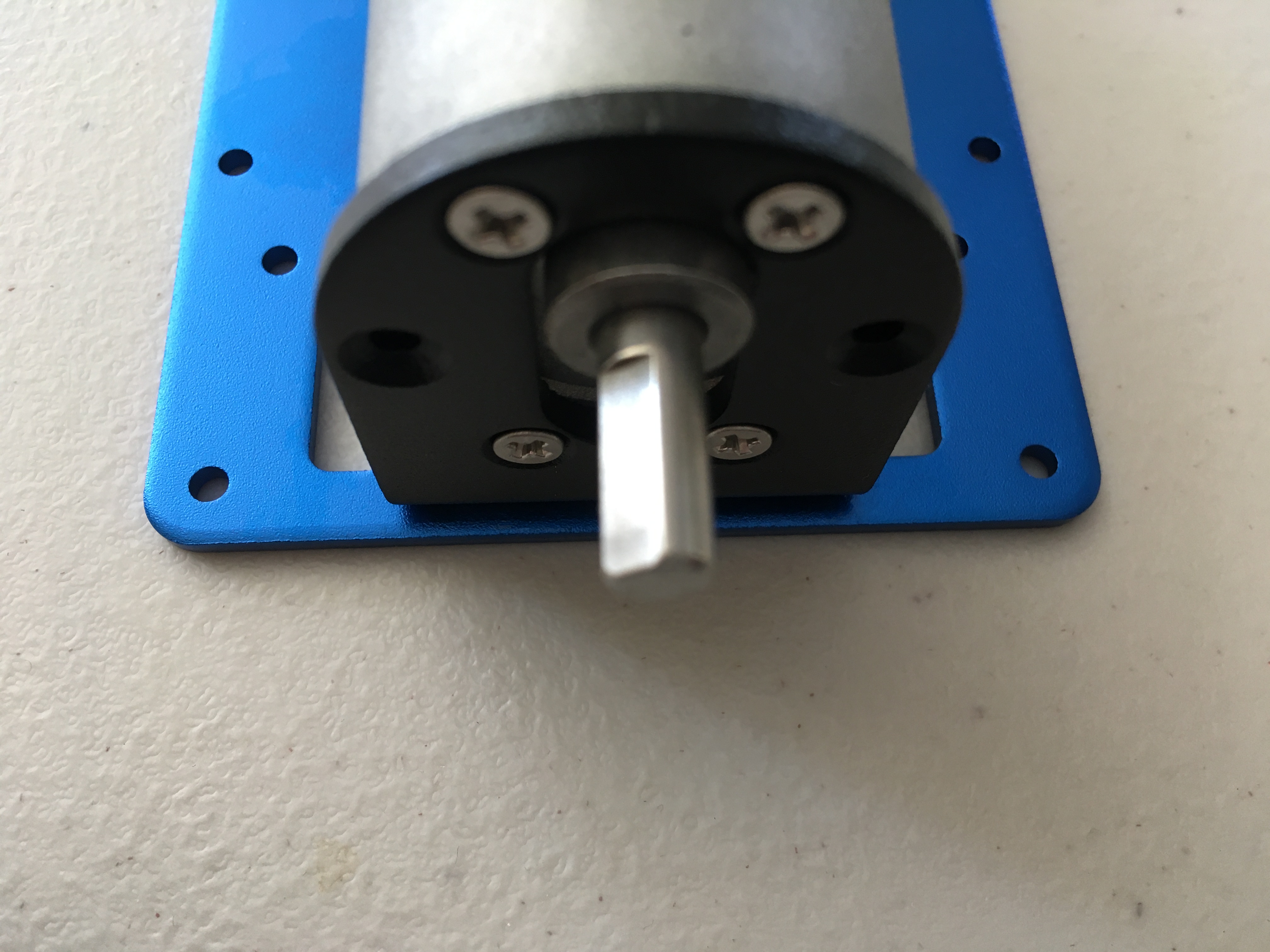
Mount the motors.


It doesn't seem to matter which side of the blue plate is up.


Only use 4 screws (top and bottom) for each motor.


Put the hubs on.
There are reports on the web of these hubs coming loose, and when
the control system starts to oscillate this is where it happens, so adding
(blue) loctite or the equivalent to the lock screws and even the axle
may be a good idea in this part of the assembly.


The shaft has a flat. Align one screw to the flat, and screw
that screw in first, so the coupling aligns with the flat.


Put the tires on.
The screws are also M4x6 from bag 3.


Put the stand on.


Get a modified controller board and a battery from the TA

Put the MPU6050 (Inertial Measurement Unit IMU) on the motherboard.


Note the standoff in the corner to support the IMU.
Front view

Note the standoff in the corner to support the IMU.
Rear view

Processor and red power electronics board are already installed.

Mount the ultrasound transducers.


Mount the controller board.


Note that the black switch and the ultrasound socket (SR04)/ultrasound
transducers on the controller board
point to the front of the robot with the plastic piece
sticking out, and the red, black, and yellow pins on the controller board
are at the rear of the robot.

Mount the standoffs for the top layers.

Mount the battery on its plate.


Mount the battery plate on robot.
First plug the battery in. Battery switch is off!


Mount the top plate.

Connect the motors to the controller board.


Check your work.


Check the lights: Pick the robot up and turn it on.
Each motor board has a green light.

Extra parts.

Put them in a bag and give them to the TA.


