IronCAD Lab - One
This lab is derived from the IronCAD tutorials. The help files and
Show_Me files are on the cluster computers. These help files are
actually helpful (unlike MicroSoft help). So if you want to find out
how to use the Sheetmetal functions in IronCAD, search for Help on
sheetmetal.
1. Getting started
Select IronCAD from the Start -> Programs ->
CAD menu. The IronCAD logo is a black I-beam on a red background:

Once you start IronCAD, you will get the following window:

Select Create a new Scene and click OK. (Drawings
are 2D and Scenes are 3D.) You will get another dialog box. This box lets you
select the background color and whether or not a grid (drawing plane) is displayed.
Select an option with a grid.

1.1. Drag and drop editing
Before we start, move your mouse to the menus at the top of the screen. Look
at the options in each of the menus. We will use only a few of these commands
in the introduction, but looking at the menus will give you a sense of the options
in IronCAD.
After you make a selection, the menu on the right will disappear. Move the
mouse close to the tab that says Shapes. The shape menu (which you can
see on the above) will reappear.
In the Shapes menu, click on the Block shape. Without releasing the mouse,
drag the block into the scene. As you drag the mouse over the scene, a small
block will follow it. (I can't show you this in a screen dump because the cursor
doesn't show up in screen dumps.)
Release the mouse. You will have a block in your drawing. Click
twice on the block. Notice that the edges of the block are
yellow. Yellow means that the part is selected.

Move the mouse around the handles (red balls) on the block. You
will see the cursor change shape and the handles change color. Put the
cursor over the top pin until it turns yellow when the cursor turns
into a hand with a two headed arrow under it:

move the cursor up and down. The part will resize along the
selected axis.

Do the same with one of the handles for the x or
y dimension.
1.2. Moving around
To get a better view of your block, go to the menu on the left and
click on the fit scene button:

While you're looking for this button, hold your cursor over the
other buttons to see the other ways you can change your view of the
scene. Try the dolly camera, orbit, pan and
zoom buttons. You probably have a strange perspective on your
block now. You can press the restore camera button, which will
return the view to the standard perspective.

To get a view of the whole block, press the fit scene button
again.
1.3. Undo and redo
Since you have performed several operations on the block, go up to the tool
buttons and press the Undo button until your block disappears.

Press the redo button until it is back to its final shape. Notice
that undo and redo only operations on the geometry.
They don't undo/redo changes in the view.
1.4. Adding shapes
Go back to the shape menu on the right hand side of the screen. Select the
cylinder shape and drag it into the scene.

Don't release the cursor yet. Move the cursor around the faces of
the block. As you move near a face, the edges of the face turn green
and the center of the face is highlighted:

With one of the faces highlighted, release the mouse. The cylinder will be
added to that side. The handles of the cylinder are automatically selected
so you can reshape the cylinder.

After you are done reshaping the cylinder, click in the background.
You can also add another cylinder to the scene that is not connected
to the block. Drag another cylinder in, and drop it away from the
block. Be sure that no points or faces on the block are highlighted
in green.

IronCAD also has negative (H) shapes. Select an H-slot from
the Shapes menu and drag it and drop it onto another face of
the block.

Add some more positive and negative
shapes to your part: Orbit your part and add/subtract shapes on all
the sides. To see what you have added to your part, and to make it
easier to select a particular sub-shape, click on the scene
browser button.

You will get a window on the left-hand
side of the screen that shows you the composition of your parts. Click
on one of the shapes, and it will be selected in the scene.

2. Making 3D shapes from 2D cross sections
Making parts using the standard shapes (called primitives) is easy,
but you won't be able to make all the shapes you want that way. Sometimes, you
will need to draw a profile and then extrude or rotate it to make a solid part.
We will only make solid parts in this class, because our goal is to make parts
that can be manufactured on the rapid prototyping equipment. IronCAD, and most
other CAD programs, also enable you to make 3D surfaces, but we will not cover
them in this class.
2.1 Creating a 2D cross section
Since IronCAD only lets you create valid 3D parts, you can't just
draw in 2D. To make a cross section, you need to start by stating
your intentions. We are going to make a balloon. My plan for the
balloon is to make a profile that looks something like the following:

and then revolve it around the vertical axis to make a solid
balloon. This is called a Spin Shape in IronCAD. In
the toolbar, you will find a set of buttons that let you extrude,
spin, sweep and loft. Press the Spin Shape tool
button.

You will get a sequence of pop up windows with the options for
creating cross sections. For all but the third menu, the defaults are
fine.
  
For the 3rd step, I changed the major grid line spacing to 0.50 inches and
the minor grid line spacing to 0.01. inches.
You will get a grid in your drawing space and pop up toolbar for
creating the profile:

Before we draw the profile for the balloon, let's look at some of the formatting
options for the grid. Select Format -> Grid.

Note that this menu item is only available when you are creating or editing
a cross section. When you select this item, you will get a popup window that
lets you control how the cross section is created. The screen dumps below show
the options for each tab in the Drawing Options window.
 
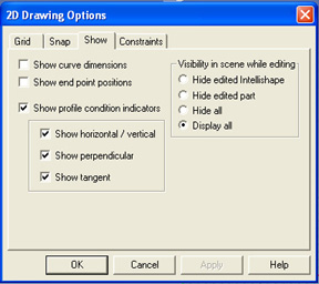 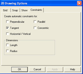
When you are done selecting the options you want, click OK. You will now have
the grid in your drawing area. Use the magnify tool on the left to zoom in on
the grid. I prefer the magnifying tool that let's me select the window to zoom
in on, but you should experiment with the different zooming options to see which
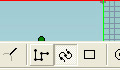
one works best for you. Once you have zoomed in on the grid, select the polyarc
tool from the bottom toolbar. This tool will let us create a sequence of arcs.
First, I clicked on the W axis to start the balloon. Then, I moved the mouse
around until I got an arc that looked right for the balloon:
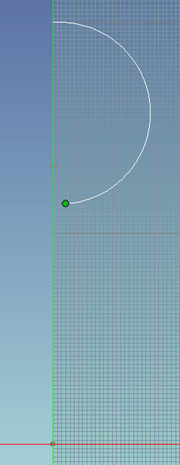
I clicked to make the arc, but because this is a polyarc, I can keep clicking
to make new segments of the the polyline:

Next, we want to make a series of lines that close the bottom of the balloon
and form the stick that the balloon is on. Press enter to end the polyarc and
press the polyline tool to start a sequence of lines. In the
options for the grid, we selected snap to geometry, so if you put the mouse
close to the end of the last arc and click, the end point of the arc and the
start point of the line will be the same point. This is important because otherwise
the balloon would have a hole in it and we wouldn't be able to revolve it. I
clicked the mouse to make a sequence of lines including one along the axis (which
doesn't show in the screen dump) to create a closed cross section of the balloon.

When you are creating a cross section, you may get an error message like the
following:

To repair the problem, select Edit cross-section. You will
get a view that lets you move the points around until the profile is valid.

When you have a valid cross section, select Finish Shape from
the cross section window. The cross section will revolve around the axis and
you will have a solid balloon:

However, if you zoom out, you will see that the balloon is lying along the
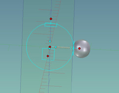
y axis. To rotate it to the z axis, we are going to use the triball.
The triball is a 3d manipulation tool that is very powerful, but takes a while
to get used to. Select the balloon and then click on the triball tool button:

The triball will appear on the part:
I have included the IronCAD help
pages on the triball and some slide shows that
take you through the steps of different operations using the triball,
so I will not include that in this part of the tutorial.
Select the x axis in the inner part of the triball. It will turn
yellow. This means that the axis is frozen - so we will be able to
rotate the part around the x axis and swing it up to the z axis.

Move the mouse on the inside of the triball until you get the
rotation hand:

Move the mouse and the part will rotate. We want to rotate exactly
90 degrees, but it's hard to stop at exactly 90°.

Right click on the numerical value of the angle. You will get a
menu that lets you edit the number:

You can enter 90 in the window that opens.
Note: We could have avoided this final rotation step by selecting
the z axis before we started the spin shape. To select the z axis,
(or whatever axis you want to rotate around) just click on it.
Next, let's move the balloon up in the air. The outer handles on
the triball are used for translation. First, lock the z axis by
clicking on the outer z handle. It should turn yellow.
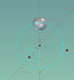
Grab the top handle with the translation hand.
Pull up on the handle until until the balloon is about 1 unit about
the x-y plane
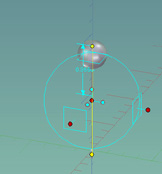
Right click on the numerical value and select edit
distance. Make the distance 1.

Finally, right click on the balloon and select SmartPaint from the menu.
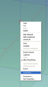
In the Smart Paint window, you can select a color for the balloon,
you can make it shiny, you can make it slightly transparent, you can
put a decoration (decal) on it, and you can make it glow slightly.
Play with the options to see how they change what the balloon looks
like.
3.Dimensions
In the first section, we just dragged in parts and resized them
without any sense of their true dimensions. This is not the way one
normally designs a part. Let's start a new scene. Our goal is to make
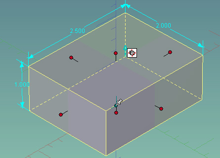
the following part:

This part is made up of two plates joined by a cylinder with holes
in the corners of both plates. The corners of the plates are
rounded. We will start by making the bottom plate with the dimensions
4.724 x 4.724 x 0.197. Then we will make a cylinder with an inner
radius of 2.212, an outer radius of 2.527 and a height of 0.591.
First, select File -> New and select
Scene from the dialog box. 
You
will get the menu that lets you select the background color and a
grid. This time, select an option with a grid. You will see the
x-y plane with a basis vector at the origin. 
3.1. Units
In order to dimension something, we need to
know what the units are. Select Format ->
Units. You will get the following dialog box. The default units
for IronCAD are English units: Inches, Degrees and Pounds. Look at
the pull down menus to see what the options are for each
attribute. 
Since the part we are drawing is in
inches and degrees, click OK.
3.2. Viewing and editing dimensions
Drag a block into the scene again. Now select
View -> Sizebox dimensions. Click to
select the block so it turns yellow, and you will see the
dimensions.

Now grab one of the handles. As you resize the block, you will
see the dimensions change. This doesn't seem like a very accurate
way to dimension a part. Select one of the handles, and right click
on the handle. If you select a face or edge instead of a handle,
you will get a different menu. Be sure that you have a handle selected
before you right click.

You
will get a box that allows you to change the length, width and height
of the box. How do you know which way the dimension will change? It
will change the dimension in the direction of the handle that you
selected.

Change the length to 2.5 and press
OK. IronCAD changes the length of the box to 2.5 by moving the
left-hand face. Select the same handle again, but this time change the
other dimensions:

This time, IronCAD resizes the block
around the anchor (the pin in the blue/green dot).
3.3. Specifying the resizing behavior
The default for IronCAD is to scale from the opposite face, but
you can change this behavior. Right click on a face of the block
and select Intellishape Properties.

You will get a dialog box with many
tabs. Take a minute to look at the options in the tabs. When you are
done, select the Anchor tab. This tab tells you the location of
the anchor. The height should be zero (i.e. the anchor should
be in the x-y plane. The anchor should be located at the mid-point of
the length and the midpoint of the width. Now select the
Sizebox tab. Notice that you can change the length, width and
height of the part in this menu. We are going to change the default
behavior of the resizing operation. Pull down the menu next to
Length and select About anchor. 
Click OK. Grab the left-hand handle again. As you move the handle,
you will see that IronCAD now resizes the length around the anchor
rather than from the opposite face. Since we didn't change the
resizing behavior for the width or height, they will still scale from
the opposite side. After you understand how this works, go back to the
Sizebox menu. (Right click on a face and select IntelliShape
Properties.) Make the default behavior to resize from the opposite
handle. Select the handle on the top face of the block and
right click. Since we have selected this handle, IronCAD will resize
the block relative to the opposite face. Since the opposite face is
sitting on the x-y plane this is what we want. (If it resized
it about the anchor, the part would extend in the negative z
direction.) Set the height of the block to 0.197. 
Click OK. 
Now we need to change the dimensions
of the length and the width. We want to scale these around the origin,
which is the default for the non-selected handles in the sizebox. So,
select the top handle again and right click to get the edit window for
the size box. Change the width and length to 4.724. 
Press the fit scene button if your part goes off the
screen. 
We will add the cylinder and top plate
before we chamfer the corners and add the holes.
4. Modifying shapes
4.1. Combining shapes
Go to the Shapes
menu and select a cylinder. Drag it to the plate. As you drag it
close to the center, the green dot will become brighter. Drop the
cylinder when the dot is highlighted. Press the fit scene
button. 
Notice that because earlier we
selected the option to show the dimension box, the dimensions are
shown for all selected parts now. You can toggle this option on and
off depending on what you are working on. Select the top handle
and right click to get the edit sizebox window. From the drawing, we
know that the height of the cylinder is 0.591 and the outer radius is
2.527. In the sizebox, set the height to 0.591. (Which direction will
it scale in?) Since the radius is 2.527, the width of the cylinder is
twice that. IronCAD will do the arithmetic for you, so you can enter
2.527*2. As soon as you enter this, the length will change to the
same value since the length and the width of a cylinder have to be the
same. 

We
still have some work to do cleaning up the cylinder and making it
hollow, but before we do that, we are going to add the plate on the
top. Select another block from the Shapes menu. Drag it
to the top face of the cylinder and drop it when the green center dot
is highlighted. 
4.2. Smart snap
We could size
the new block the same way we did the first one; however, IronCAD has
an extremely useful feature, called Smart Snap, that we will
illustrate with this part. Hold the shift key down and pull on
the left-hand handle. As you pull it toward the edge, you will first
see the edge of the cylinder highlighted and then the edge of the
bottom plate. 
Release the mouse when the edge or
face of the bottom plate is highlighted. The face of the new block is
now co-planar with the face of the lower block. Do the same thing
with each face. Use the orbit tool to see and change the other
faces. 
Now all we have to do is change the
height of the top plate. Select the top handle. (Which direction will
IronCAD resize in?) Right click and change the height to 0.197. 
4.3. Subtracting shapes
Next, we want to get rid of the
material of the cylinder that's hanging out over the edges. What we
are going to do is to use a negative block (H-block) and put it where
we want to remove the material. Go the Shapes menu and select an H
block. Drag it to the left hand end of your part. Drop it when the
green dot at the midpoint of the edge is highlighted. (The screen dump
of this doesn't show anything interesting. You will just have to do
it.) When you drop the H-block, IronCAD will take a chunk out of the
part. This is not what we want! 
Select the H-block. (If you can't select it, select the scene
browser and select the H-block from the tree.) Drag the left hand face
of the H-block to the left. Drag the bottom face so that it extends
beyond the bottom of the part. Now we are going to use Smart Snap
again. Press the shift key, and drag the right-hand handle toward the
edge of the part. When the edge of the lower plate is highlighted,
release the mouse. The negative block has subtracted the
overhang. Perform the same operation for all the sides. (If you watch
the tutorial, you will learn how to use the IronCAD triball, but this
lab is getting long, so you can do that on your own. 

Now
let's make the hole for the center of the cylinder. Go to the
Shapes catalog to the right of the drawing area and select the
H-cylinder. Drag it and drop it on the center of the top plate. Be
sure the green dot that marks the center of the top face is
highlighted when you drop the shape. 
The
inner radius of the cylinder is 2.212. So, select the top handle and
right click to get the size box. Enter 2.212*2 for the width of the
H-cylinder.

After you press enter, your part should look like:

5. Views, textures, colors, ...
To get standard views of your part (e.g. top, right, isometric,
etc.), select Tools -> Standard
Views. You will get a separate toolbar that has buttons for the
standard views.

Using this toolbar should make it easier to get the view of your
part that you want.
Here is my final part after I applied the blend, dragged the fire
texture to the surface of the part, and selected the standard
isometric view.

To see other options for the color of a part, right click on the
part and select SmartPaint from the popup menu.

As you go through the SmartPaint tabs, you will see that the fire
texture is implemented as a reflection on a solid white surface. Try
changing the color, finish, transparency, emission, etc. of your
part. You can click the Apply button to see the effect of the
change without closing the menu.
Note: If you have only one face selected (i.e. the face
outline is highlighted in green), the color changes will apply only to
that face. In the following screen dump, I made one face flat green,
another face 50% transparent blue and applied the play decal to the
third face:

Note: You should not paint your parts like this!


sfinger@ri.cmu.edu
| 
