Building a LEGO Turing Machine
In this article, I illustrate how to build a (slightly) modified version of the LEGO Turing machine built by researchers at CWI.

Introduction
Internship
A month ago, I started my summer internship at Software Engineering Institute, Carnegie Mellon working on verification of concurrent programs with Dr. Arie Gurfinkel and Dr. Sagar Chaki. We looked for an interesting example to demonstrate our verification tool and to learn how we can imporve it.
LEGO Mindstorms & nxtOSEK
Interestingly, Arie and Sagar have used concurrent programs written for LEGO Mindstorm as benchmarks of their verification tool. At first time, I got an impression that these LEGO programs are not realistic. However, I learned that I was wrong.
- Those LEGO Mindstorms programs are running on the nxtOSEK platform.
- A part of nxtOSEK is TOPPERS/ATK, which provided real-time multi tasking features proven in automotive industry.
- Actually, “OSEK” in “nxtOSEK” is an open standard for automotive embedded systems, published by a consortium founded by the automobile industry including BMW, Robert Bosch GmbH, DaimlerChrysler, Opel, Siemens, Volkswagen Group, Renault and PSA Peugeot Citroën.
- nxtOSEK’s real-time kernel is also compatible with μITRON 4.0 specification which is a de-facto industry standard in the embedded systems field.

Sometimes, things are more than what we see. This Mindstorms car looks like a toy, however it contains a complex embedded system inside.
CWI Turing Machine
After spending some time on searching for good examples, I found this fascinating Turing machine which was designed by researchers at CWI. I do recommend their [Video] if you have not watched it yet.

We decided to build this machine because of the following reasons:
- Simple Mechanics: All operations — reading, writing, and moving — can be done by simply rotating motors and reading a sensor. We do not need to worry about complex movements which are basically not our interest.
- Inherent Parallelism: Though the CWI TM is a single-thread program, it is natural to program a Turing machine using multiple threads.
0. Required Components
- LEGO Mindstorms NXT 2.0 Kit (8547) (
$280): Definitely, we need this one. This kit consists of one NXT brick, three servo motors, and four sensors (ultrasonic sensor, 2 touch sensors, and color sensor). To build this TM, we are going to use three servo motors and one color sensor. 
- Technic Parts ($20): It is not clear what components you really need even after reading the CWI webpage. They just mention that you need some other parts from LEGO Technic Kits. Watching their video several times, I figured out what we needed to build a machine with a 16-bit long tape.
| Number | Name | Quantity |
|---|---|---|
| 3647 | Technic Gear 8 Tooth | 5 |
| 3713 | Technic Bush | 40 |
| 3743 | Technic Gear Rack 1 x 4 | 10 |
| 3737 | Technic Axle 8 | 10 |
| 4274 | Technic Pin 1/2 | 25 |
| 4716 | Technic Gear Worm | 2 |
| 6536 | Technic Cross Block 1 x 2(Axle/Pin) | 15 |
| 32014 | Technic Angle Connector #6 (90 degree) (BLACK!) | 15 |
| 48989 | Technic Cross Block 1 x 3(Pin/Pin/Pin) with 4 Pins | 10 |
Please note that you have to choose Black color when you buy 32014 Technic Angle Connector #6 (90 degree) because this part will be used as a bit in a tape.
1. Tape (16-bit)
Let’s build the tape first. Basically, 32014 Technic Angle Connector #6 (90 degree) — the L-shaped black part — plays the role of “bit”. Two bits are separated by either a 3713 Technic Bush — Red cylindrical object — or 6536 Technic Cross Block 1 x 2(Axle/Pin).

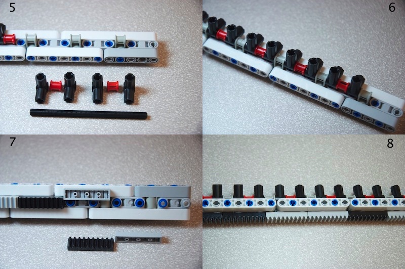
The bottom of the tape is not shown on the Video and it is actually quite tricky to figure out what there is. As you see in image 7 and 8, there are 3743 Technic Gear Rack 1 x 4 at the bottom of the tape, which are attached with 4274 Technic Pin 1/2.
2. Rail & Bridge

Building a rail and a bridge is not difficult. Make sure that the gap in the rail is three-hole wide so that the tape can fit in it.
3. Engine (Gears & Gear Worms)
This is the most interesting part of the machine. Here is a problem. We need linear movement to move the tape back and forth while our servo motor only provides circular movement. The CWI design solves this problem by using gear, gear worms, and gear racks.
My solution is simpler than the CWI design in a sense that mine does not use a bevel gear.

Note that there are some inconsistencies between picture #4 and #6 (Thanks to Serj Smorod). There are two grey upper bricks on the left side (#4) and on the right (#6). You should take #4.
Once you finish up to step 6, please make sure that the gear worms do not move back and forth when you rotate the 24-teeth black gear.

You also need to place additional 3647 Technic Gear 8 Tooth on the rail to hold the tape stably (see the top and bottom parts of Engine #2 image).
4. Tape Mover
We need to transfer the drive from a motor to the engine part. First assemble the Tape Mover unit with a servo motor.

Then attach it to the bridge and engine part. Make sure that there is no movement of the motor when it runs.

5. Reader
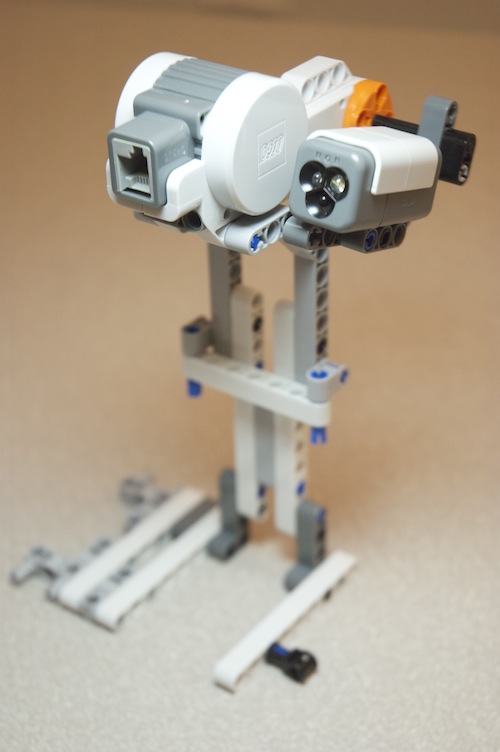
The Reader unit consists of one servo motor and one color sensor. Once you assemble it, attach to the rail & bridge.

6. Writer

The Writer unit has a servo motor with a lever to flip a bit. It is important to align the Reader and Writer well so that they can read and write the same bit of the tape.

That’s it!
Once you finish all the steps, connect all the motors and the sensor to the NXT brick using cables. Now, you are ready to run this machine!
