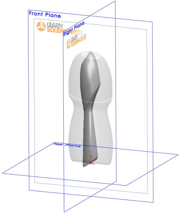
Surfaces
This exercise is reproduced from Jan-Willem Zuyderduyn's
"How
to Model A Deodorant Roller in SolidWorks?" tutorial from
LearnSolidWorks.com.

Reference Images
- Make a Deodorant folder and download the files frontview_deoroller.jpg and
sideview_deoroller.jpg to that folder.
- Start SolidWorks.
- Make a new part.
- Set the units to millimeters.
- Make a new sketch on the Right plane.
- Go to Tools > Sketch Tools > Sketch Picture and insert the sideview_deoroller.jpg image. Choose Low Resolution.
- Set the picture properties as follows:
- Turn off Enable Scale Tool.
- Turn on Lock Aspect Ratio.
- x origin -55.00 mm
- y origin -22.00 mm
- leave the angle at 0 deg
- x size 106.50 mm
- y size will self-adjust
- transprency: "Full Image", set to 0.40
- Click OK.
- Close the sketch.
- Make new sketch on the Front plane.
- Go to Tools > Sketch Tools > Sketch Picture and insert the frontview_deoroller.jpg image. Choose Low Resolution.
- Set the picture properties as follows:
- Turn off Enable Scale Tool.
- Turn on Lock Aspect Ratio.
- x origin -53.00 mm
- y origin -22.00 mm
- leave the angle at 0 deg
- x size 106.50 mm
- y size will self-adjust
- transprency: "Full Image", set to 0.40
- Click OK.
- Close the sketch.
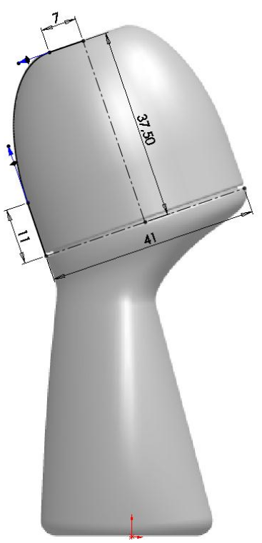
Cap
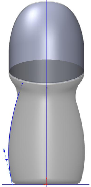
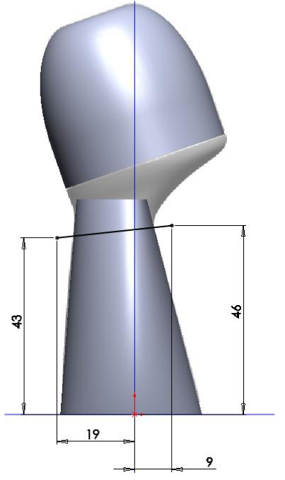
- Make a new sketch on the Right plane.
- Add two centerlines as shown.
- Add two line segments, and connect them with a spline without any midpoints.
- Add tangent relations between the spline and the line segments.
- Adjust the spline to match the reference image. You will only be able to change the lengths of the arrows, not the angles, due to the tangent relations.
- Close the sketch.
- Make sure the Surface tab is visible. If not, right click on any tab and select Surface.
- Create a Revolved Surface feature from the sketch.
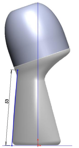
Body
- Create a new sketch on the Right plane.
- Draw the 53 mm line as shown. The bottom point should be horizontal to the origin.
- Close the sketch.
- Rename the sketch to GUIDELINE_FRONT.
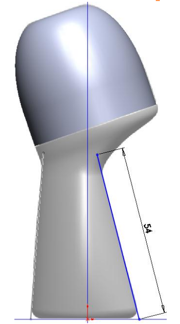
- Create another sketch on the Right plane.
- Draw the 54 mm line as shown. The bottom point should be horizontal to the origin.
- Close the sketch.
- Rename the sketch to GUIDELINE_BACK.
- Create a new sketch on the Front plane.
- Draw a spline without midpoints as shown. The bottom point should be horizontal to the origin.
- Change the arrows to approximate the outline of the body.
- Close the sketch.
- Rename the sketch to GUIDELINE_SIDE.
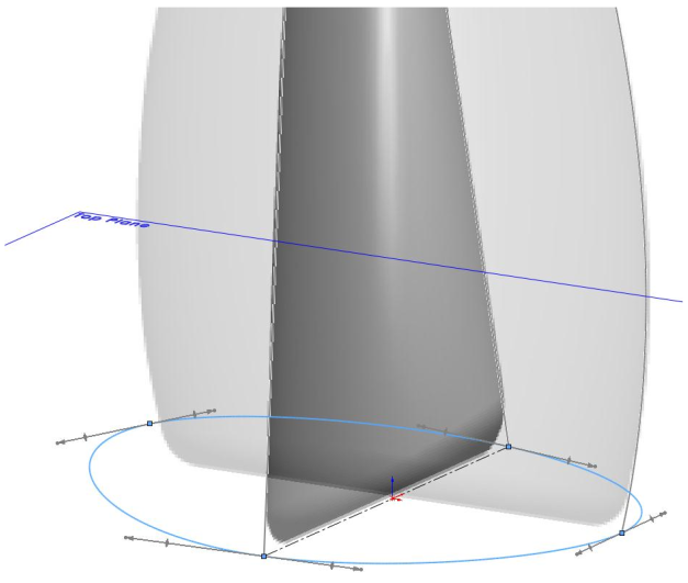
- Create a new sketch on the Top plane.
- Draw a centerline connecting the front and back guidelines.
- Draw a closed oval spline with four points, three of which intersect the guidelines.
- Select the spline point not on a guideline, shift-click on the
centerline, then shift-click on the opposite point (on the side
guideline). Add a Symmetric relation.
- Close the sketch.
- Rename the sketch to PROFILE.
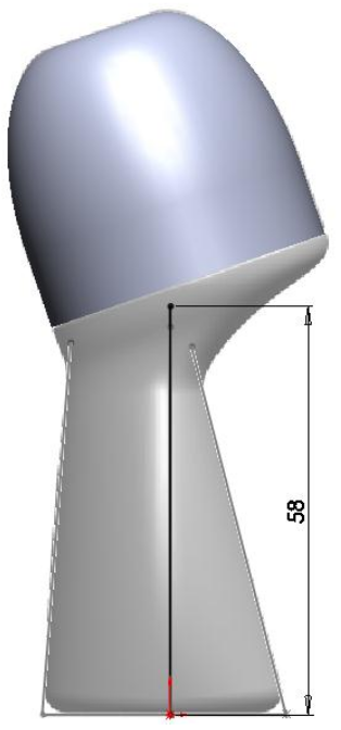
- Create a new sketch on the Right Plane.
- Draw a 58 mm line up from the origin.
- Close the sketch.
- Rename the sketch to PATH.
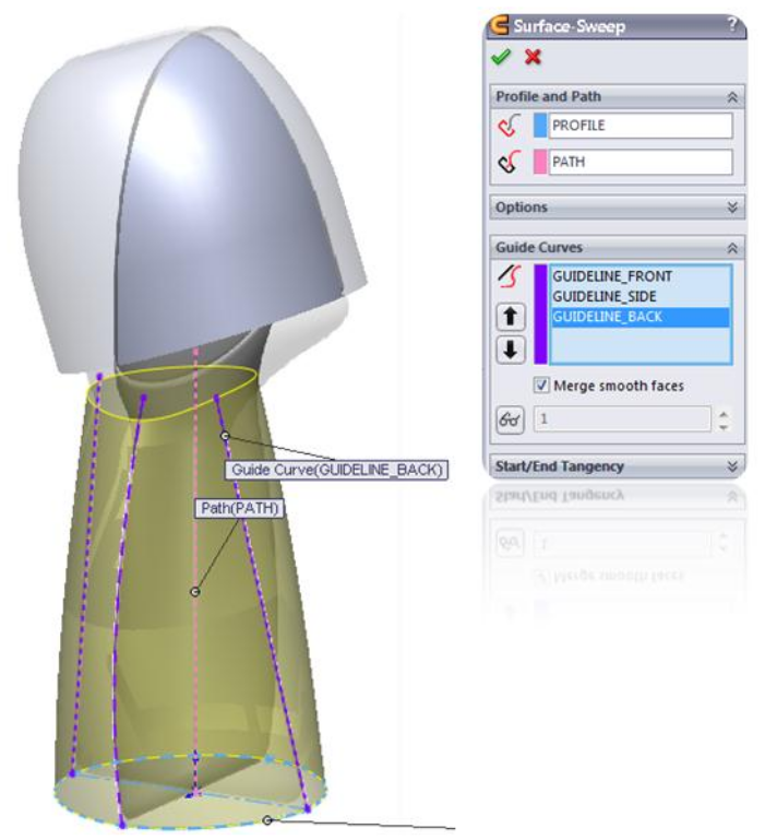
- Create a Swept Surface feature.
- Select the PROFILE sketch as the Sweep Profile.
- Select the PATH sketch as the Sweep Path.
- Select the three GUIDELINE sketches as the guidelines curves.
- Click OK.
Trim the Top of the Body
- Create a new sketch on the Right plane.
- Draw the cut line as shown.
- Close the sketch.
- In the Surface tab, select Trim Surface.
- For the Trim Tool, select the sketch you just made.
- Choose Remove Selections.
- Set the Surface Split Options to Natural.
- Click on the part of the body above the trim line; it should turn orange.
- Click OK.
Create the Neck
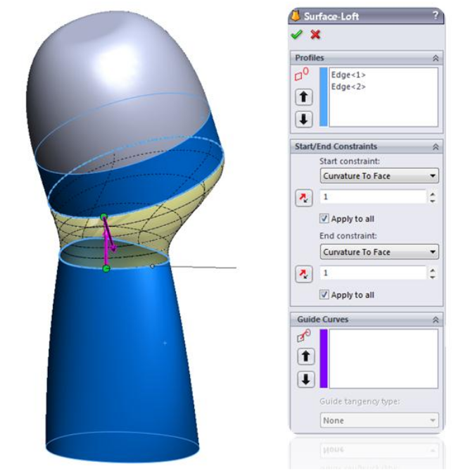
- Create a Lofted Surface feature.
- In the Profiles box, select the bottom edge of the cap and the top edge of the body.
- Make sure the green balls are aligned.
- Click on the Start/End Constraints box.
- Set both constraints to Curvature to Face.
- Change the length of the purple arrows to adjust the shape of
the loft. Adjust it to match the profile in the image.
- Click OK.
- Turn off visibility of the sketches with the images.
Fill the Bottom
- Create a Filled Surface feature.
- Click on the bottom edge of the body.
- Click OK.
Knit the Surfaces and Create a Solid Body
- Create a Knit Surface feature.
- Select the cap, neck, body, and bottom surfaces.
- Turn on Create Solid.
- Turn on Merge Entities.
- Turn off Gap Control.
- Click OK.
- Fillet the bottom edge of the body with a radius of 2 mm.
Cut the Cap Gap
- In the Features Tab, open Reference Geometry and create an Axis.
- Select the Cylindrical/Conical Face option.
- Click on the cylindrical (bottom) segment of the cap.
- Click OK.
- Create a new sketch on the Right plane.
- Draw the rectangular cutting profile as shown. Make sure the right edge extends past the end of the neck surface.
- Close the sketch.
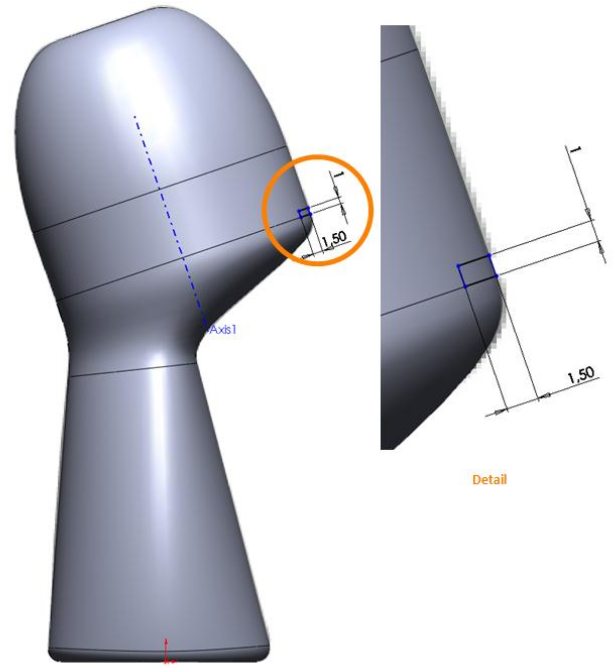
- Insert a Revolved Cut feature using the sketch and the axis.
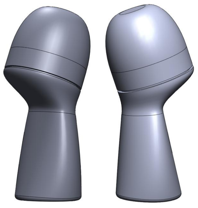
Color and Save
- Color the cap turquise and the rest of the part white.
- Save the file as Deodorant.SLDPRT.
- Make a rendering of your part.
