Articulation
- Download the Compound.zip file and
extract the contents. This contains all the parts you need for this
exercise, so you can skip down to the Gear Assembly step. If
you would prefer to construct the parts yourself, keep reading.
Spur Gears
- Create a new folder called Compound.
- Download SpurGear-6-20.SLDPRT from the web and save it in Compound.
- Open SpurGear-6-20 in SolidWorks.
- Do "Save As Copy and Open" and save the part as SpurGear-12-20.
- Click on Manage Equations and set the pitch diameter to 12.
- Edit the hole sketch and set all the hole distances to 0.45 inches.
- Save the part.
- Do "Save As Copy and Open" and save the part as SpurGear-12-40.
- For SpurGear-12-40, click on Manage Equations and set the number of teeth to 40.
- Save the part.
- Create a new part called GearSpacer: a disk 1.25 inches in diameter.
- Add 1/8 inch holes, one at the center and one 0.45 inches above it.
- Save the part.
- Make a BackingPlate part 6 inches by 6 inches.
- Add three 1/8 inch diameter holes in an L-shape, spacing 2.5 inches.
- Save the part.
Gear Assembly
- Make an assembly and insert the BackingPlate.
- Insert a SpurGear-12-20 and mate it to the left hole.
- Insert a SpurGear-12-40 and mate it to the right hole.
- Add a 20:40 gear mate.
- Insert a new SpurGear-12-20 and mate it to the top of the
SpurGear-12-40 using both holes, so that the two gears are
rigidly attached.
- Insert GearSpacer into the assembly and mate it to the top hole in the backplate.
- Insert a new SpurGear-12-40 and mate it to the top of the Spacer using both holes.
- Add a 40:20 gear mate betweeen the new SpurGear-12-40 and SpurGear-12-20 instances.
- Verify that rotating the left gear results in a 4:1 reduction for the top gear.
- Verify that rotating the top gear produces a 1:4 speedup in the bottom gear.
Articulation 1
- Download the Articulation.zip
file and extract the contents. This contains all the parts you need
for this exercise.
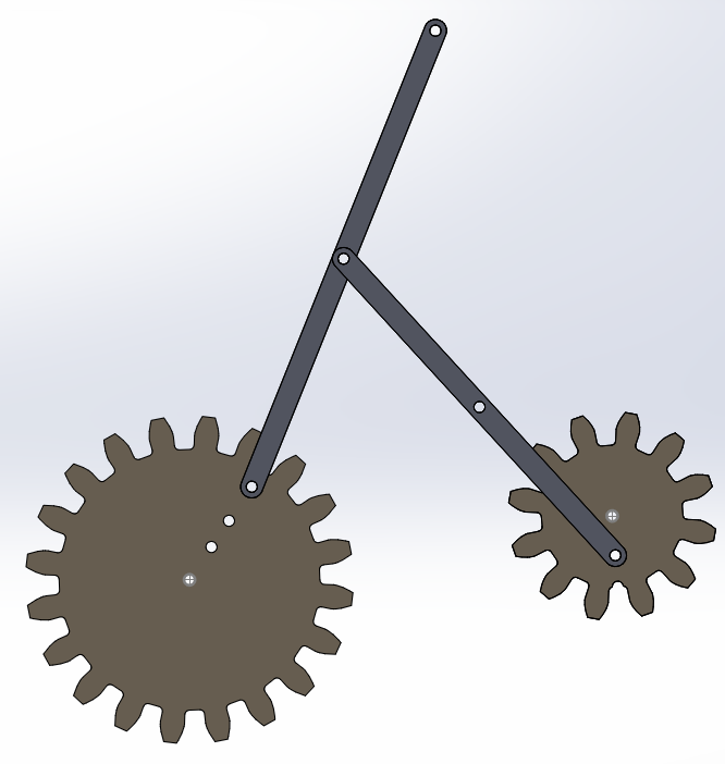
- In a fresh SolidWorks, make a new assembly.
- Insert a SpurGear-6-20 and a SpurGeart-6-12 and mate their backs to the Front plane.
- Position the gears so they roughly match the diagram above.
- Create a new sketch on the Front Plane.
- From the back side of the gears, click on the center hole of the large gear. Then click on Convert Entities.
- Click on the center hole of the small gear, then click on Convert Entities.
- Exit the sketch.
- Mate each gear to the corresponding circle in the sketch.
- Add a 20:12 gear mate between the gears.
- Insert a LongBar part and mate one end of it to the large gear.
- Insert a Spacer and mate it to a hole in the small gear.
- Insert a ShortBar and mate one end to the spacer.
- Mate the other end of the short bar to the center hold of the long bar.
- Rotate the gears to verify that the bars move freely. If they
get stuck, change the positioning of the gears by editing the sketch
and moving the circles.
- Turn on the Motion feature and turn off Simulation.
- Go to the Motion Study tab and set the mode to Motion Study.
- Insert a motor to rotate the large gear at 40 rpm.
- Click calculate to simulate the mechanism.
- Click on the Reports icon above the timeline.
- Select Displacement/Velocity/Acceleration as the major type and Trace Path as the minor type.
- Select the hole in the distal end of the long bar as the point to
track.
- Observe how changing the positioning of the gears changes the
shape of the plotted trajectory.
Articulation 2
- Start a fresh assembly.
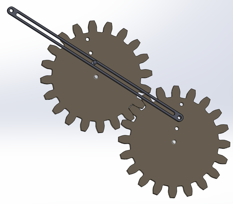
- Insert two SpurGear-6-20 parts.
- Mate their back faces to the Front Plane.
- Position the gears so that their teeth mesh.
- Create a new sketch on the Front Plane.
- Use Convert Entities to copy the center hole of each gear onto the sketch.
- Exit the sketch.
- Mate the center hole of each gear to the corresponding hole in the sketch.
- Create a 20:20 gear mate between the two gears.
- Insert a Pin part.
- Mate the bottom edge of the pin to the bottom of the hole closest to the center hole in the left gear.
- Insert a SlottedBar.
- Mate one hole in the SlottedBar to the third hole (counting from the center outward) of the right gear.
- Create a slot mate between the pin and the slot.
- Turn one gear and verify that the link moves freely.
- Go to the Motion Study tab.
- Insert a motor to turn one gear at 40 rpm.
- Add a solid body contact between the pin and the slot of the SlottedBar.
- Click calculate to simulate the mechanism.
- Add a Results plot to trace the path of the top hole of the
SlottedBar.
Articulation 3
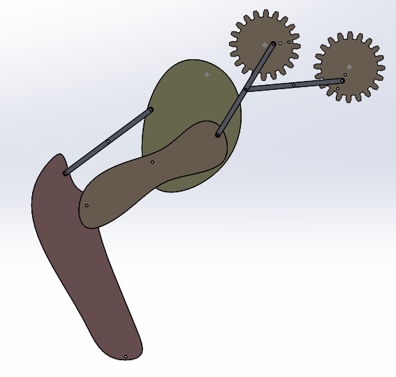
- Load the LegBacking.SLDASM file.
- Insert two SpurGear-6-20 parts and mate them to the indicated holes in the sketch.
- Insert a Spacer and mate it to the left gear on the hole closest to the center hole.
- Insert a Thigh part and mate the top hole to the indicated hole in the sketch.
- Insert a Calf part and mate its middle hole to the bottom hole of the Thigh.
- Insert a LegBar1 and mate one end to the spacer on top of the left gear.
- Mate the other end of the LegBar1 to the top hole of the Calf.
- Insert a LegBar2 and mate one end to the third hole in the right gear, counting
outward from the center hole.
- Mate the other end of the LegBar2 to the middle hole of the LegBar1.
- Insert a Foot and mate its middle hole to the bottom hole of the Calf.
- Insert a LegBar1 and mate it to to top hole of the Foot.
- Mate the other end of the LegBar1 to the middle hole of the Thigh.
- Go to the Motion Study tab.
- Add a motor to rotate one gear to 40 4pm.
- Click on calculate to simulate the model.
- Add a Results plot to trace the path of the hole at the distal end of the foot.
- To change the camera view in a motion study, first slide the time index to 0.
- Reposition the view of the model as desired.
- Right click on the black diamond in the "Orientation and Camera
Views" row and select "Replace Key".
Dave Touretzky
Last modified: Wed Mar 29 16:44:49 EDT 2017