Kangaroo 2 Physics in Grasshopper
What is Kangaroo 2?
Kangaroo 2 is a physics engine for Grasshopper that solves constraint
satisfaction problems.
It is a substantial redesign of the original Kangaroo. Be careful
when looking at online tutorials: much of what you see in a Kangaroo
tutorial will not work directly in Kangaroo 2.
Deforming a Mesh
- In Rhino, do Surface > Plane > Corner-to-Corner and draw a rectangle in the x-y plane.
- Set the view to Shaded.
- In Grasshopper, add a Surface parameter and set it to the surface you made in Rhino.
- In Grasshopper, go to the Display menu and turn on "Preview Mesh Edges".
- Add a Move component to move the surface away from the Rhino object. Right click on the
T input to Move and do Set One Vector to set up the move.
- Add a Mesh > Util > Mesh Surface component and feed the Move result into it.
- Add two number sliders as 2 < 20 < 40 and connect them to the U and V inputs of the Mesh Surface component.
- Add a Kangaroo2 > Main > Bouncy Solver.
- Create a Button and feed it into the Reset input of the Bouncy Solver.
- Create a Kangaroo2 > Main > Show component and run the
output of Mesh Surface into it. Note that Show labels both its
input and output as "G", but the input is Geometry and the output is
Goals.
- Connect the output of Show to the GoalObjects input of Bouncy Solver. Disable preview of earlier components.
- Run the O output of the Bouncy Solver into a List Item
component. Disable preview of the Bouncy Solver and display the
Mesh output.
- Note that the O output only contains a mesh at this point, so the List Item seems superfluous. This will change in the next step.
- Add a Kangaroo2 > Goals-Mesh > Edge Lengths component below the Show component.
- Use shift-click to add the output of the Edge Lengths component to the Goal Objects input of the solver.
- Add a number slider as 0.00 < 0.50 < 1 and connect it to the Length Factor input of the Edge Lengths component.
- Observe that the mesh shrivels up. Press Reset to observe this again.
- Note that the O output of the solver now contains multiple objects.
- Add a Surface > Analysis > Deconstruct Brep component, and feed the Move output into it.
- Observe that the Vertices output has four points.
- Add an Kangaroo2 > Goals-Pt > Anchor component below the Edge Lengths component and
connect the Vertices output of Deconstruct Brep to it.
- Use shift-click to add the output of the Anchor component to the goals input of the solver.
- Observe that the mesh is now anchored at the corners.
- Add a Mesh & Analysis > Deconstruct Mesh component, and feed the output of Mesh Surface into it.
- Feed the Vertices output of Deconstruct Mesh into a List Item component.
- Add a Panel and double click on it to edit; set the contents to 240, 241, 242, and 243, each on a separate line. Righ click on the panel and turn off Multi-Line Data. These numbers assume that the U and V sliders are set to 20.
- Feed the output of the panel into the i input of List Item.
- Add a Kangaroo2 > Goals-Pt > Load component and feed the output of List Item into its P input.
- Add a 0 < 0.1 < 10 number slider and feed its output into a Vector > Vector gt; Unit Z component.
- Set the output of the Unit Z component to FV input of the Load.
- Use shift-click to add the output of the Load component to the goal objects of the solver.
- Play with the load slider and observe the deformation of the sheet.
- Add a Mesh > Util > Smooth Mesh component and run the solver's mesh output (selected
via the List Item) into its mesh input.
- Create a 0 < 0.50 < 2.00 number slider and feed it into the S input of Smooth Mesh.
- Create a 1 < 5 < 25 number slider and feed its output into the I input of Smooth Mesh.
- Observe that making either number slider value too large causes the mesh to go crazy.
- Bake the smoothed mesh and move it off to the side.
- Insert a Kangaroo2 > Mesh > Naked Vertices component and feed the output of Mesh Surface into it.
- Run the NakedPts output of Naked Vertices into a Points parameter so we can observe the points.
- Use shift-Click to add the Points parameter's output to the P input of the Anchor component.
- Observe that the sheet is now anchored all along its edges.
- Increase the Load number slider and observe the deformation change.
- Bake the final mesh and move it off to the side.
- Save your Grasshopper program.
Deforming a Poly-Surface
- Start a new Grasshopper file and a new Rhino file.
- In Rhino, make a Solid > Box > Corner-to-Corner-Height.
- Set the View to Shaded.
- Use control-shift-click (command-shift-click on the Mac) to
select and then delete the bottom face of the box and two opposite side faces.
- In Grasshopper, add a Surface parameter and you'll find you cannot set it to the Rhino object, which is a Brep.
- You cannot set a Mesh parameter to the Rhino object either.
- Replace the Surface and Mesh parameters with a Brep parameter and set it to the Rhino object.
- Insert a Move component to move the Brep away from the Rhino object.
- Unlike the previous example, we cannot implicitly convert this
Brep into a mesh because it is actually three NURB surfaces, not
one. So we have to do a little more work.
- Add a Surface > Analysis > Deconstruct Brep component and feed the Move into it.
- Create Mesh > Util > Mesh Surface component and feed the
Faces output of Deconstruct Brep into its Surface input. Note that
there are 3 faces, so the output is 3 meshes. This is not what we
want. We want one continuous mesh.
- Each mesh has U and V divisions, but we can't control which is
U and which is V, so if we want to allow unequal U and V divisions,
but we also want the meshes to align with each other, we have to do
a little extra work.
- Create a 2 < 20 < 40 number slider and below it, a 2 < 3 < 40 number slider.
- Create a List Item component and feed both number sliders into its L input.
- Right click on the i input to List Item, do Set Multiple Integers, and input the values 0, 0, 1.
- Make a copy of the List Item component, and in the copy, set the i values to 1, 1, 0.
- Feed the first List Item output to the U input the Mesh Surface
component, and the second List Item output to the V input.
- Observe that the three meshes are properly aligned.
- In Rhino, control-shift-click on an edge of the surface to select it. Then click and drag to change
the shape of the box.
- You can also control-shift-click on a point and select polyline-vertex, then drag the point.
- Notice that the meshes remain aligned. But they are still 3
separate meshes.
- Add a Weaverbird > Extract > Join Meshes and Weld component, and feed the output of Mesh Surface into it. Set the Weld input to True.
- Now we can use Kangaroo2 to deform this mesh much like the previous exercise.
- Add a Kangaroo2 > Main > Bouncy Solver, and feed its O output to a List Item component.
- Feed the output of the welded mesh into a Kangaroo2 > Main
> Show component and feed that into the Bouncy Solver's goal objects list.
- Feed the welded mesh into a Kangaroo2 > Goals-Mesh > Edge
Lengths component and add its output to the solver's goal objects.
- Create a 0 < 0.50 < 1 number slider and feed it into the Length Factor input of Edge Lengths.
- Add a Kangaro2 > Mesh > Naked Vertices component, feed
the welded mesh into it, and feed its NakedPts output into a
Kangaroo2 > Goals-Pt > Anchor component, whose output should
be added to the solver's goal objects.
- Add a Mesh > Util > Smooth Mesh component and feed the List Item into it.
- Set the Smooth Mesh component's S input to a 0 < 0.50 < 1 number slider, and
the I input to a 1 < 5 < 25 number slider. Set Skip Naked Edges to False.
- Bake the result and move it aside.
- To get the meshes to align perfectly you can use panels to specify indexes for U and V values for all
the planar meshes that make up your complex shape.
- You may need to add additional anchor points to prevent the
shape from collapsing too much. You can use a Mesh > Mesh
Edges component to pull out the naked edges of a mesh as a set of
lines then use Curve > Analysis > End Points to pull out the
points, and you can turn them into anchors using an Anchor
component with a lower strength than the regular anchors.
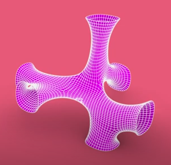
Deforming A Complex Shape
- Load the kanga-pipe.3dm file into Rhino.
- To learn how to make this mesh, see this page.
- Make a Mesh parameter in Grasshopper and set it to the perfect mesh object in Rhino; ignore the other meshes.
- Feed the Mesh parameter into the Weaverbird Join Meshes component, replacing its previous input.
- Bake the output and move it to the side.
|