SolidWorks Intro Part 1
Dave Touretzky
Starting Up
- Log in using your Andrew ID.
- Use the Start button, search for and run program: "Solidworks 2018 x64"
First Time With SolidWorks
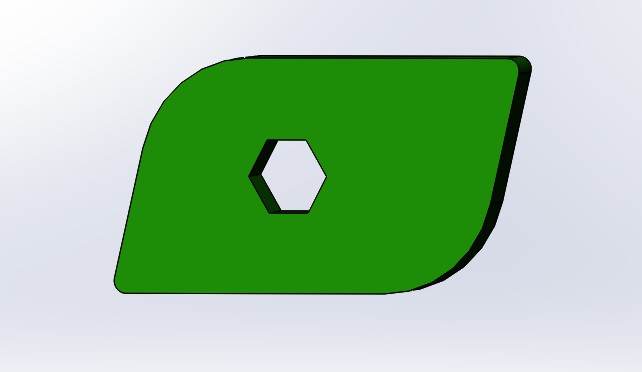
We'll make this part:
- If the SolidWorks Resources fly-out menu is visible on the right side, click in empty space to collapse it.
- New part
- Use IPS as default units
- Extruded base
- Select front plane
- Select rectangle tool
- Note different types of rectangle available; stick with the default.
- Move mouse and note snap-to lines above or beside the origin.
- Draw a rectangle away from the origin, about 1.5 in wide by 1 in high.
- Note the rectangle tool is still active.
- Green checkmark to confirm, or escape to exit the rectangle tool.
- Click on the polygon tool.
- Draw a hexagon lying entirely inside the rectangle.
- Notice the snap-to lines as you move the mouse.
- Hit escape to exit the polygon tool.
- Look in the top right corner for the Exit Sketch icon.
- Click on Exit Sketch.
- Now we've popped back to the Boss-Extrude dialog.
- Change the depth to "1/8 in", which matches our acrylic.
- Look in the top right for the green OK checkmark, and click it.
- Look at the Feature Manager Tree:
- The root is Part1.
- Notice the Boss-Extrude1 feature.
- Mouse buttons:
- Left click on a face to select the feature and bring up a shortcut menu.
- Left click in empty space (or hit Escape twice) to deselect.
- Scroll wheel to zoom.
- Middle button to rotate about screen-x and screen-y.
- Alt-middle button to rotate about screen-z.
- Control-middle button to translate.
- COMMON MISTAKE:
- Use the scroll wheel to zoom WAY past the part so you can't see it.
- Rotating won't help.
- Scrolling won't help if you don't know which way to go (in or out).
- Type "f" to fit the part in the window. Easy fix!
- Or click on the "zoom to fit" icon at the top of the screen.
- Let's go back and edit the sketch again. Three ways to do it:
- i) Left click on a face.
- ii) Left click on the feature in the Feature Manager tree.
- iii) Open the feature (click on the "+" sign) and click on the sketch icon that will appear below it.
- All of these bring up a shortcut menu.
- Select the edit sketch icon from the menu.
- Type a <space> to get the views menu and select "normal to".
- DO THIS ONCE:
- Right click on a blank spot in the Sketch toolbar to get a pop-up menu.
- Click on "Customize..." at the bottom.
- Go to the Commands tab.
- Click on Standard Views.
- Click and drag the "Normal To" tool to the sketch toolbar.
- Click OK to close the Customize window. You can also use control-8 as a keyboard shortcut for Normal To.
- Back to editing our sketch:
- Click "Normal To" or type control-8.
- Click on the right vertical line.
- Look at the properties tab.
- Select the "Vertical" relation and delete it.
- Grab the top right point and drag it; now we have a quadrilateral.
- Control-Z to undo.
- Control-Y to redo.
- Escape to exit.
- Click on the Exit Sketch icon.
- Rotate the part so you can see the corner edges.
- Switch to the Features tab.
- Click on the top right edge and select the Fillet tool.
- Set fillet radius to 0.05 in.
- Add the bottom left edge, but not the other two edges.
- Click on a FACE to see what happens. Click again to de-select.
- Click the green checkmark to accept.
- Look in the Feature Manager tree and see two features: Extrude1 and Fillet1.
- Create a new fillet feature for the top left and bottom right corners; set the radius to 0.5 in.
- Complete the fillet by clicking OK.
- Click on a face and select the Appearances icon.
- In the appearances pop-up menu, click on the part name.
- Select a color from the pallette and click OK.
- Grab the rollback bar and roll back the two fillets.
- Then roll it down again to bring back the fillets.
DIMENSIONING
- Edit the sketch again.
- Click on the Smart Dimension tool.
- Select the left vertical line and set its length to 1 inch.
- Select the bottom horizonal line and set its length to 1.6 inches.
- Select the right line and then the top line, and set their angle to 75 deg.
- Select the circle inside the hexagon and set its diameter to 0.3 inches.
- Escape to exit the Smart Dimension tool.
RELATIONS
- Edit the sketch again.
- Click Normal To.
- Click on the left vertical line; observe the Line Properties.
- Shift-click on the right vertical line; now two lines are selected.
- Click on the Equal relation.
- Observe the error, then click on the OK checkmark in the property editor.
- Click on the left vertical line.
- Click on its Vertical property and hit Delete to remove it.
- Click OK to accept the sketch. Looks nice!
- Edit the sketch again.
- Click Normal To.
- Drag the bottom left point to the origin.
- Notice that the parallelogram has turned black. No lines are draggable.
- The parallelogram is now "fully defined".
- Click on one line of the hexagon.
- Give it the Horizontal property.
- Click on the Smart Dimension tool.
- Click on the point at the center of the hexagon, then on the bottom line.
- Set the distance to 0.48 inches.
- Escape to exit.
- Click on the Smart Dimension tool again.
- Click on the point at the center of the hexagon again.
- Now click on the origin point.
- Slide the mouse around and watch the dimension change type.
- Bring the mouse horizontal in line with the point to get a horiz. dimension.
- Set this dimension to 0.8 inches.
- Now the sketch is fully defined.
- After you've completed a dimension, you can click and drag to reposition it.
- Click Exit Sketch.
- Click on File -> Save As and save your part as MyFrob.SLDPRT.

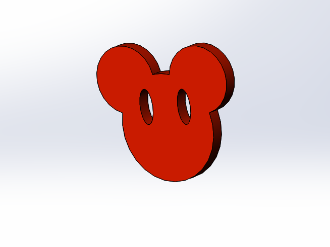
Now we'll make this part:

- New Part
- Extruded Base on the Front Plane.
- Make a circle centered on the origin, radius roughly 1 inch.
- Click Exit Sketch, set extrude depth to 1/8 in, and click OK.
- Now we want to make another sketch on the Front Plane...
- Click Extruded Base.
- Open up the object tree by clicking the + next to the Part name.
- Select Front plane.
- Get a normal view by typing space and clicking on the Normal icon (or type control-8).
- Make smaller circle above and to the left of the big one, radius roughly 0.27 inches, that intersects the first circle somewhere in the top left quadrant.
- On the line tool pulldown menu, select Centerline.
- Draw a centerline straight up from the origin for about 1.5 inches.
- Notice the line property: "for construction", indicated visually by dashes.
- Hit Escape to exit.
- Click on the Mirror Entities tool.
- Select the small circle for Entities to Mirror.
- Click in the Mirror About box and select the centerline.
- Click OK to complete the mirror.
- Click and drag on either small circle to change the size.
- Click and drag on the center of either small circle to change position.
- Click OK to accept the sketch, and set depth to 1/8 in.
- Click on Extruded Cut.
- Click on the face of the part.
- Draw a vertical ellipse to serve as an eye for the face:
- Click on the ellipse tool.
- Click to indicate the center of the ellipse.
- Move mouse down to adjust the size.
- Click again to accept the size.
- Move mouse to the right to adjust the width.
- Click one more time to accept the width.
- Add a centerline as before.
- Mirror the ellipse.
- Click and drag on the bottom point of the ellipse to tilt the eyes.
- Click Exit Sketch.
- In the Cut Extrude dialog, change Blind to Through All.
- Click OK.
- Set the part appearance to red.
- Save your part as Mickey.SLDPRT.
