|
|
15292
SPRING 2020
|
Due: Monday, February 17 by 9:00AM
In the 1960s and 1970s (and even beyond), mini-computers were a new way to get into the world of computing without being tied to the large mainframes from manufacturers such as IBM. Mini-computers were smaller, requiring only a small part of a room, and these machines were designed so that users could create their own programs more easily than before.
Digital Equipment Corporation was the leading manufacturer of mini-computers, particularly with their PDP series, the most famous being the PDP-8. In this assignment, you will work with a PDP-11 simulator online to enter in a few programs as the console operator would. Note that the PDP series had the means to attach a punched tape reader and have the machine read much more elaborate programs from punched tape, but the programs you will write are relatively short so you can enter them directly on the PDP-11 front console. This assignment will give you the experience of programming in the early days when you had to enter code in the machine's language which you will see is very tedious and error-prone. (Have fun!)
The simulator is available to run at this website:
https://skn.noip.me/pdp11/pdp11.html
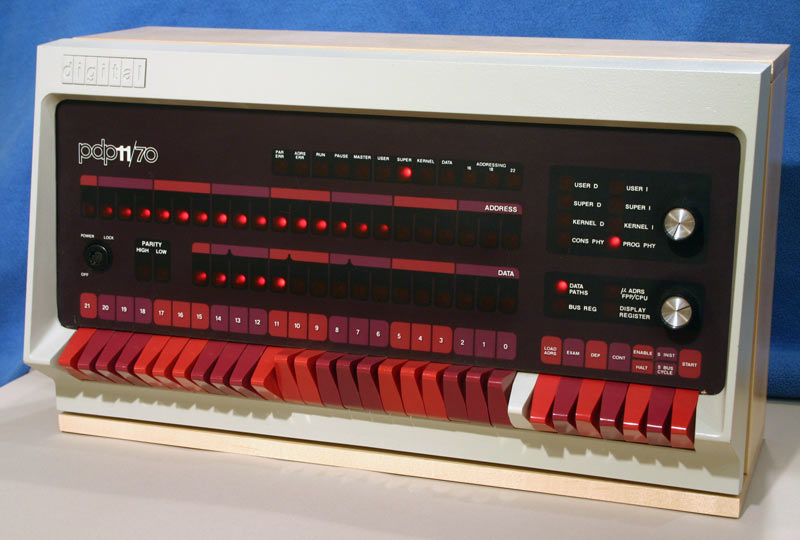
Here is a picture of the front console from the simulator with some notes on some of its features. (We will not explore the entire machine.)
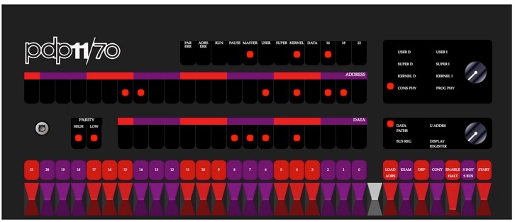
On the console, there are three rows of lights. The first row shows some monitoring functions for the computer, such as RUN (lit when a program is running). The second row shows the address of a word of memory and the third row shows the data stored at that address in memory. NOTE: The address and data are shown in OCTAL (base 8)!!! Every group of three lights represents an octal digit:
binary   000  001  010  011  100  101  110  111
octal      0    1    2    3    4    5    6    7
For example, in the picture above, the current address being displayed is 001401 in octal (0 000 001 100 000 001) and the data displayed is 000720 in octal (0 000 000 111 010 000). We will not use the leftmost 6 lights of the Address lights.
Below the lights are a set of 22 numbered entry switches that toggle (try them out by clicking them). These line up under the address and data rows so you can enter in an address or data value. We will not use switches #16 through #21; leave them as is.
There are also command switches at the bottom right:
LOAD ADRS (Load Address) - Loads the current setting of the entry switches into the Address lights.
EXAM (Examine) - Displays the data currently stored at the address displayed in the Address lights.
DEP (Deposit) - Stores the current setting of the entry switches into the next available Address based on the Address lights.
CONT (Continue) - Continue running the program where it had stopped last.
ENABLE/HALT - Enable the program for execution, or halt the program.
START - Start the program beginning at the address shown in the Address lights.
When you start the simulator, you will see that the machine boots up with a computation being performed on the data lights.
In this assignment, you will enter two additional programs and get them to run. To demonstrate that you have entered the programs, you will record your work into a video that you will submit, along with a text file that answers some simple questions about the simulator and your work. You should practice your work first to make sure that you can do it with little to no errors so that your video is as short as possible. Store the answers to the questions given below in a plain ASCII text file named pdp11answers.txt.
Address  Data    Code
001000   012700  mov #1, r0    (move the value 1 into register 0)
001002   000001                (the value 1 for the previous command)
001004   006100  rol r0        (rotate register 0 left one position)
001006   000005  reset
001010   000775  br .-4        (branch back 4 words, goto address 001000)
To enter this program, follow these steps:
Before you run your program, you should check to make sure each address has the correct data:
If all of the data values are correct, move on to the next step. Otherwise, go back and start over.
Now you can run your program:
You should see a single light in the Data section that races around and around. Congratulations! You just entered and ran your first PDP-11 program.
Record your process of entering, checking and running the program into a video in MP4 or WMV format and name this lightchaser.mp4 or lightchaser.wmv. Practice a few times so that your video does not contain errors or wasted time. Please try to keep your video short.
In your text file pdp11answers.txt, answer the following question: To make the light race to the right instead of left, you need to use the ror command (rotate right). How would this command be encoded at octal address 001004? (Hint: look in the PDP-11 Handbook in Chapter 4 for a list of PDP-11 instruction codes.)
Address  Data    Code
001000   013702  mov @#sr, r2 (start)
001002   177570  switch register
001004   005000  clr r0
001006   005001  clr r1
001010   005200  inc r0 (loop)
001012   060001  add r0, r1
001014   020002  cmp r0, r2
001016   001374  bne loop (branch if r0 != r2 to loop)
001020   010100  mov r1, r0
001022   000000  halt
001024   000765  br start (branch to start instruction to execute again)
Enter this program in the same manner as you did in the previous problem. Once entered, follow the steps in the previous problem to check your data entries to make sure they're correct before you try to run the program. (You must be very careful and deliberate here... it's VERY easy to make mistakes!)
Once you are certain the program is entered correctly, run the program to compute the sum of the first 50 positive integers:
Your program should run and halt, displaying the result in the Data lights. In your text file pdp11answers.txt, show that the results are correct by converting the final answer (shown in binary/octal) back to decimal. Show your work.
You should record your process of entering, checking and running the program into a video in MP4 or WMV format and name this sum_to_n.mp4 or sum_to_n.wmv. Practice a few times so that your video does not contain errors or wasted time. Please try to keep your video short.
OTHER FACTORS
Zip up all files (two videos and a text file) and hand in to Autolab.
Assignments will be graded out of 100 points. For maximum credit (100 points), your videos must show correct entry, checking and execution of the two programs along with correct answers for the four questions posed. Points may be deducted for videos that run excessively long.
Submissions may be handed in up one lecture late with a 20% penalty.
Many thanks to Paul Nankervis for the simulator and retrocmp.com for the sample programs!