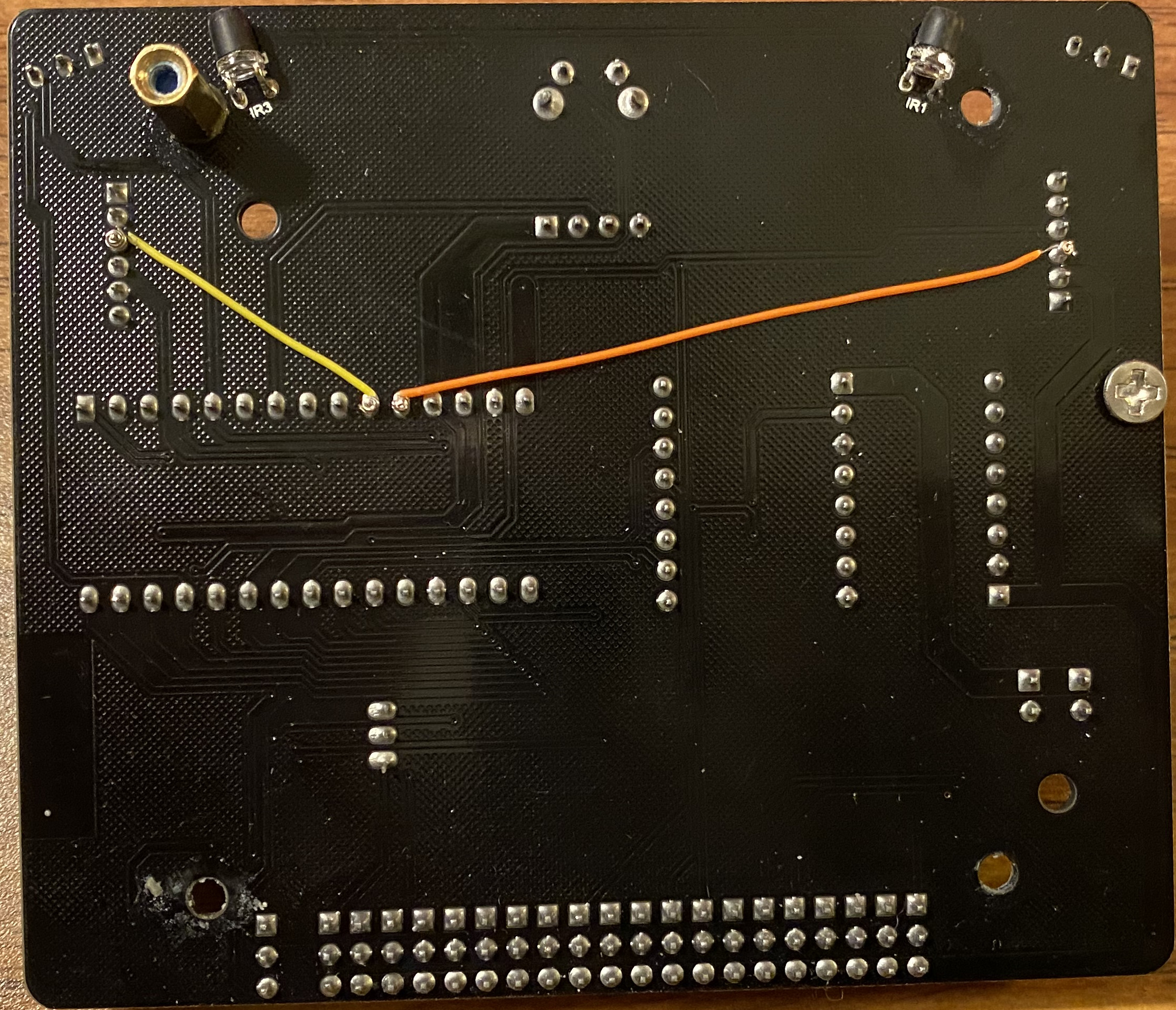
One can also solder wires instead of using wire wrap.
First, a hardware modification. I used wire wrap technology to run wires
from the B pin on the motor connectors to the A6 and A7 pins on the Nano.

One can also solder wires instead of using wire wrap.
Second, I swapped the Nano board to the Nano Every board. The Nano board doesn't seem to reliably take digital inputs or cause pin change interrupts on pins A6 and A7. The Nano Every can do external interrupts on all pins including A6 and A7. The Nano Every also has more memory.
Swapping the CPU from an ATmega328P (Nano) to an ATmega4809 (Nano Every) turned out to have some implications:
The encoder zero is arbitrary, so you may need to "calibrate" that in your code. The encoder is digital so its scale factor does not need to be calibrated.
The PWM frequency on Arduinos is about 500Hz. There is no point in trying to generate motor driver commands at a faster rate. There may be beat frequency effects between the servo frequency and the PWM frequency.
The IMU (MPU6050) accelerometer and gyro readings have a bias that drifts over minutes. You should calibrate the biases at least at the start of every session you work with the robot, and perhaps before each experiment. I don't see the need to calibrate the scale or linearity of these sensors.
Statically, the command to the motor driver is proportional to the motor current, and that is proportional to the motor torque. However, there is a large amount of static friction. One could try to calibrate the command to torque relationship by using the wheel as a pulley that holds up a weight. You can easily generate several weights by using a container that holds various amounts of water. Motor inductance and back EMF make it more difficult to estimate the motor current from the motor drive command when the motor is moving.