
You are required to write your own code for this project. While you may discuss the project with your fellow students, you may not borrow code from anyone else.
Another problem has to do with the leak current. The leak conductance is constant; there is no rise or fall. The paper shows a tfall value of 9 msec because this is a nice trick for getting the conductance to come out to the desired value of 111 nS; it shows no trise value. When writing your gi conductance function you will need to handle the leak current as a special case. You can set its trise to NaN when you define the current to mark this case.
currents whose first entry,
for the AHP current, looks like this:
In this example,c.AHP = 1; currents(c.AHP).tau_rise = 1e-4; currents(c.AHP).tau_fall = 30; currents(c.AHP).G = 23; currents(c.AHP).Erev = -90; currents(c.AHP).anorm = find_anorm(currents(c.AHP));
find_anorm is a function that computes
anorm, which is a function of tmax. You will find it
advantageous to declare c and currents to
be global variables. Also, read
this page of modeling advice for
info on how to structure your MATLAB code. NOTE: Changes to parameter values: For the ADP current, use tau_rise = 135 - 1e-4, and tau_fall = 135. For the theta current, use tau_fall = 8. For the gamma current, use G=150.
The table of parameters in the paper shows the leak conductance as 111, but the text says that gleak = C/τleak, which might lead you to infer that the value should be 1/9 = 0.111. They messed up on the units. The 111 value is correct. In general, don't worry about getting the units right; just use the numbers in Table 1.
Create a struct array to describe the set of pyramidal cells in your model. Two values you must keep for each cell are: its current membrane voltage V, and the time it last emitted a spike. You may wish to keep additional values around, such as a state indicator (normal, spiking, or refractory), the cell's current total conductance, and the most recent voltage adjustment, ΔV.
At the start of your simulation you will specify the number of
pyramidal cells P, and the length of the simulation run in
milliseconds. Assume that time starts at t=0 and advances in
increments of Δt = 1 msec. From this you can calculate the
number of steps S in the simulation. Create a history array
Vhist of size P × S that will hold the
membrane voltage of each pyramidal cell at each time step. You will use
Vhist for plotting the results of your simulation.
Write a function updatePyramid(p,t) where p is the
pyramidal cell number (from 1 to P) and t is the current time step
(from 1 to S). Your function should compute the new membrane voltage
V(t+Δt) based on the previous voltage V(t) and the current
conductances gi(trel), where trel is
the time relative to the most recent spike. (Depending on the
current, this might be the most recent theta spike, gamma spike, or
the cell's own spike.) Start with a very simple cell that just has a
leak current.
Write the first version of the main loop of your simulation. It should progress through all the time steps, recalculating the membrane voltage of each pyramidal cell at each step. Set the cell's initial membrane voltage to something other than the resting potential of -60 mV. When the main loop finishes, plot the membrane voltage history and verify that the cell settled to its resting potential.
Theta modulation from the medial septum is simulated by a series of
theta "spikes"; each spike triggers an inhibitory conductance. Create
an array thetaSpikes of size S containing, for each
entry, the time of the most recent theta spike. (At a theta frequency
of 8 Hz, the last theta spike time should stay the same for 125 msec,
then jump ahead by 125 msec., etc.)
Extend your updatePyramid function to include the theta
current. Rerun the simulation and verify that theta ipsp's are
present.
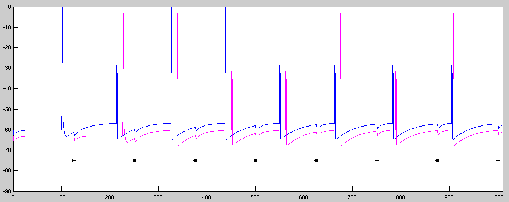
In the example plot above, created with P=2 (two pyramidal cells) and an S value of around 510, the black asterisks mark theta cell spikes. You can see that each theta spike briefly hyperpolarizes the pyramidal cells due to the inhibitory conductance. The two pyramidal cells have identical membrane voltages, but the traces are offset vertically in the plot so that they won't be right on top of each other.
inputSpikes that contains the last spike time of an input
to each of the P pyramidal cells. These spikes will control an
"input" current whose parameters are not listed in Table 1, but you
can find them on p. 3 of the "Reverse and Forward Buffering" paper;
use 0 mV as the reversal potential.
Modify the updatePyramid function to include the AHP,
ADP, and input currents, and add logic to make the cell spike if the
membrane voltage goes above threshold. When the cell enters the
"spiking" state it should hold its membrane voltage at 0 mV for 1
millisecond; then it should enter a refractory state for 2
milliseconds where it refuses to spike no matter what the membrane
voltage is. When the refractory period is over, the cell should
return to its normal state and can spike again if the membrane voltage
goes above threshold.
Write a function setInput(p,ts) that sets up an input
spike for pyramidal cell number p at time ts by writing appropriate
values into the inputSpikes array. You call this
function at the beginning of your simulation for each input spike you
want to apply. Note that since inputSpikes(p,i) encodes
the time of the last spike up to and including step i of the
simulation, when you add a spike to the array you must modify all the
succeeding entries on that row.
Set up an input spike for the first pyramidal cell at time t=100, and run your simulation with two cells. Verify that the first cell fires repeatedly while the second one remains inactive, but both cells show theta ipsps. Note: you must set the firing rate threshold to -57 mV rather than the -50 mV value given in the paper.
Now set up an input to the second pyramidal cell at time t=225. Run the simulation again. Notice that the relative spike times of the two pyramidal cells are not stable. We will fix this in the next step.
To implement the gamma interneuron you will need to create a variable
gammaNeuron containing the same kind of structure as a
pyramidal cell. (There is only one of these interneurons in the
simulation so you don't need an array of them.) This neuron should
receive excitatory input from the pyramidal cells, which you can model
as a single input current using the last spike time of the most
recently-fired pyramidal cell.
Write an updateGamma function to update the state of the
gamma interneuron, using the appropriate parameters for that neuron instead
of the ones for the pyramidal cell.
Modify your updatePyramid function to include inhibitory
input from the gamma interneuron. Modify your display code to display
the gamma interneuron's firing.
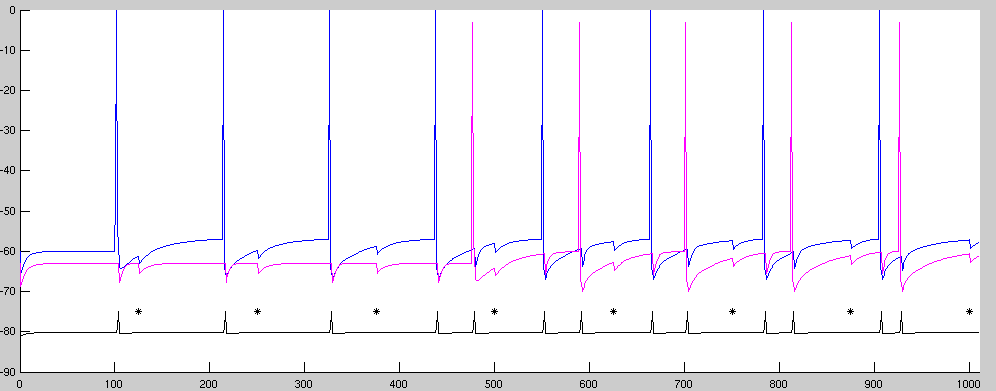
In the above plot, the black asterisks mark theta cell spikes, and the membrane voltage of the gamma cell is shown as a black line. The first input is at t=100 msec and the second at t=475 msec. The gamma cell trace is scaled and translated downward to get it out of the way of the pyramidal cell voltage traces.
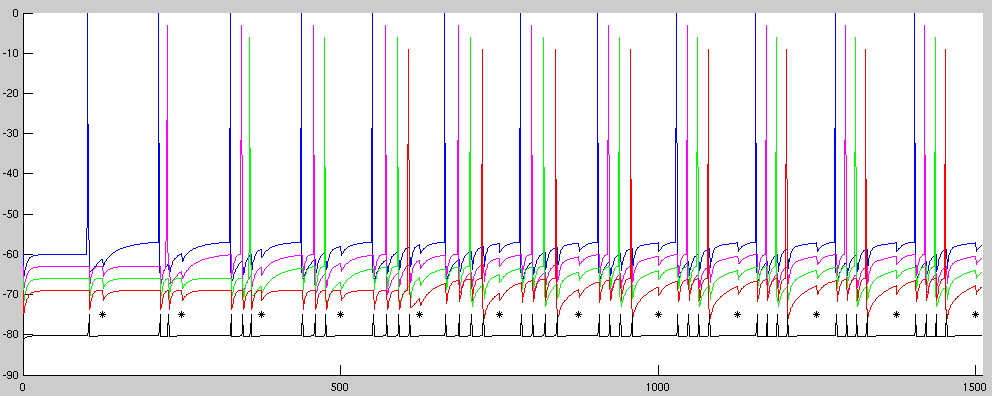
Run your simulation with four pyramidal cells for 1510 time steps. Input should come at t=100 for the first cell, t=225 for the second, t=355 for the third, and t=605 for the fourth. Verify that the relative spike times are stable.
spikestats that is called after the simulation has run,
and prints out the following statistics separately for each pyramidal cell: