We assume that the reader is familiar with classical AI planning, but in this section we will highlight the main concepts and relate them to the PbR framework. Weld [82,83] and Russell & Norvig [69] provide excellent introductions to AI planning.
PbR follows the classical AI planning representation of actions that transform a state. The state is a set of ground propositions understood as a conjunctive formula. PbR, as most AI planners, follows the Closed World Assumption, that is, if a proposition is not explicitly mentioned in the state it is assumed to be false, similarly to the negation as failure semantics of logic programming. The propositions of the state are modified, asserted or negated, by the actions in the domain. The actions of a domain are specified by operator schemas.
An operator schema consists of two logical formulas: the precondition, which defines the conditions under which the operator may be applied, and the postcondition, which specifies the changes on the state effected by the operator. Propositions not mentioned in the postcondition are assumed not to change during the application of the operator. This type of representation was initially introduced in the STRIPS system [31]. The language for the operators in PbR is the same as in Sage [48,47], which is an extension of UCPOP [65]. The operator description language in PbR accepts arbitrary function-free first-order formulas in the preconditions of the operators, and conditional and universally quantified effects (but no disjunctive effects). In addition, the operators can specify the resources they use. Sage and PbR address unit non-consumable resources. These resources are fully acquired by an operator until the completion of its action and then released to be reused.
Figure 2 shows a sample operator schema specification for a simple Blocks World domain,4 in the representation accepted by PbR. This domain has two actions: stack, which puts one block on top of another, and unstack, which places a block on the table.5 The state is described by two predicates: (on ?x ?y)6 denotes that a block ?x is on top of another block ?y (or on the Table), and (clear ?x) denotes that a ?x block does not have any other block on top of it.
|
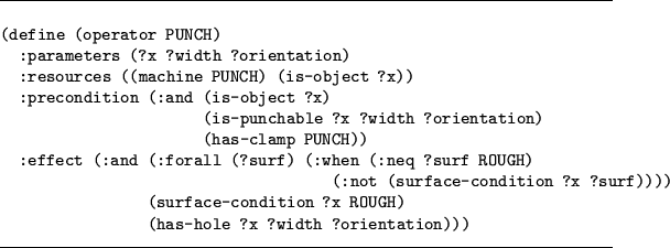
An example of a more complex operator from a process manufacturing domain is shown in Figure 3. This operator describes the behavior of a punch, which is a machine used to make holes in parts. The punch operation requires that there is an available clamp at the machine and that the orientation and width of the hole is appropriate for using the punch. After executing the operation the part will have the desired hole but it will also have a rough surface.7 Note the specification on the resources slot. Declaring (machine PUNCH) as a resource enforces that no other operator can use the punch concurrently. Similarly, declaring the part, (is-object ?x), as a resource means that only one operation at a time can be performed on the object. Further examples of operator specifications appear in Figures 18, 19, and 28.
A plan in PbR is represented by a graph, in the spirit of partial-order causal-link planners (POCL) such as UCPOP [65]. The nodes are plan steps, that is, instantiated domain operators. The edges specify a temporal ordering relation among steps imposed by causal links and ordering constraints. A causal link is a record of how a proposition is established in a plan. This record contains the proposition (sometimes also called a condition), a producer step, and a consumer step. The producer is a step in the plan that asserts the proposition, that is, the proposition is one of its effects. The consumer is a step that needs that proposition, that is, the proposition is one of its preconditions. By causality, the producer must precede the consumer.
The ordering constraints are needed to ensure that the plan is consistent. They arise from resolving operator threats and resource conflicts. An operator threat occurs when a step that negates the condition of a causal link can be ordered between the producer and the consumer steps of the causal link. To prevent this situation, which makes the plan inconsistent, POCL planners order the threatening step either before the producer (demotion) or after the consumer (promotion) by posting the appropriate ordering constraints. For the unit non-consumable resources we considered, steps requiring the same resource have to be sequentially ordered, and such a chain of ordering constraints will appear in the plan.
An example of a plan in the Blocks World using this graph
representation is given in Figure 4. This plan transforms an
initial state consisting of two towers: C on A, A on the Table, B on
D, and D on the Table; to the final state consisting of one tower: A
on B, B on C, C on D, and D on the Table. The initial state is
represented as step 0 with no preconditions and all the
propositions of the initial state as postconditions. Similarly, the
goal state is represented as a step goal with no postconditions
and the goal formula as the precondition. The plan achieves the goal
by using two unstack steps to disassemble the two initial towers
and then using three stack steps to build the desired tower. The
causal links are shown as solid arrows and the ordering constraints as
dashed arrows. The additional effects of a step that are not used in
causal links, sometimes called side effects, are shown after each step
pointed by thin dashed arrows. Negated propositions are preceded by
![]() .
Note the need for the ordering link between the steps 2, stack(B C Table), and 3, stack(A B Table). If step 3 could be
ordered concurrently or before step 2, it would negate the
precondition clear(B) of step 2, making the plan inconsistent. A
similar situation occurs between steps 1 and 2 where another ordering
link is introduced.
.
Note the need for the ordering link between the steps 2, stack(B C Table), and 3, stack(A B Table). If step 3 could be
ordered concurrently or before step 2, it would negate the
precondition clear(B) of step 2, making the plan inconsistent. A
similar situation occurs between steps 1 and 2 where another ordering
link is introduced.