Timeline box
What is a Timeline box

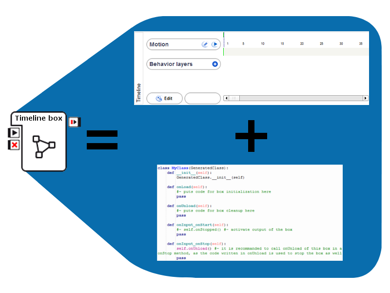
A timeline box is a box which includes a script and a timeline.
Thanks to its timeline, a timeline box may contain both movements and boxes.
How to create a Timeline box
To create a Timeline box:
Right click on your diagram wherever you want to create the box.
Click on Add a new Box in the context menu.
The Create a new box menu is displayed.

Add a name and a tooltip for your box.
Optional: set the picture to recognize it among other boxes in your diagram.
Optional: set parameters, inputs and outputs that can be manipulated by the box. For further details about parameters, see How to add/remove inputs, outputs, parameters in a box section.
In the box type part, select Timeline.
Click on Ok.
The created Timeline box is displayed on the diagram.
If you double click on your box to get into it, a timelime view is displayed and will store all the movement keyframes.

Timeline panel
The Timeline panel is displayed when you double-click on a box which is a timeline box:

It enables you to edit the timeline of the box. It contains contains 3 parts:
- The Motion area.
- The Behavior layers area.
- The Details area.
Motion area

This area contains the motion layer of the timeline, which basically represents the movements NAO is going to execute.
Numbers above the timeline enables you to get your bearings within the timeline. They represent the numbers of the frames.
The start frame is represented by the green flag on the left (1). The end frame is represented by the red flag on the right (2).
You can set both of them to a specific frame or reset them to default by right-clicking on a frame number and selecting the right option (set the frame here or reset it).
Each motion keyframe is represented by a dark grey rectangle in the timeline.
You can insert a new motion keyframe with the robot’s current position to a frame by right-clicking on the frame in the grey timeline area and selecting Store joints in keyframe. Then select the joints you want to store the value of (whole body, head, arms, legs or forearms).
You can select a motion keyframe simbly by clicking on it. You can select several motion keyframes by dragging and dropping in the grey timeline area. And you can select all motion keyframes by right-clicking on the grey timeline area and selecting Selection > Select all. A motion keyframe gets orange when it is selected.
Note
The option Select from layer enables you to select only the keyframe stored for a selected joint. To know how to use this option, see the Timeline Editor section.
The values of left and right joints can be swapped using the Mirror option in the right-click menu. Then you can select where to apply the swap (whole timeline, selected frames, selected keys). For example if the robot moves his right arm during the whole timeline and you mirror it, then it will move his left arm from now on instead.
You can move motion keyframes within the timeline by simply dragging and dropping them. They can also be cut, copied, pasted and deleted through the right-click menu.
Note
Before pasting a selection of motion keyframes, be sure to select the frame where you want to paste it. To do so, click on the frame you want to select within the grey timeline area.
If the keyframe you have pasted is empty, this could mean that there is a conflict with contradictory values for the same joint at this frame.
Motion keyframes can be exported to clipboard by right-clicking on them and selecting Export motion to clipboard. There you can select the language you want to export the motion into. Now you can paste the code in your code and the robot will make the same movements when this code is executed.
The values of some joints can be removed from any motion keyframe by right-clicking on it and selecting Remove joints from keyframe. Then select the joints you want to remove (whole body, head, arms, legs or forearms).
If you keep your mouse on a motion keyframe, then a tooltip appears with the values of stored joints.
More generally you can select a frame by clicking on it within the grey timeline area. The robot will automatically take the position corresponding to this frame. The currently selected frame is represented by the blue line (3).
You can even select a range of frames by dragging and dropping on the frame numbers. The currently selected range of frames is represented by a blue square surrounded by purple triangles as follows:

You can then use the left purple triangle to move the selected chunk of motion layer. You can use the right purple triangle to resize the selected chunk of motion layer.
Note
Since a chunk of motion layer may contain motion keyframes, they are moved as the selection is moved. They also adapt themselves to the new size of the selection. As the size of the selection grows, the duration between keyframes grows too.
There are 2 buttons on the left of the area:

The first leads to the Timeline Editor which enables you to edit the motion layer in details for each joint.
The second enables you to play only the motion layer of the timeline to give you a good preview of the animation. When the timeline is being played, the time cursor is represented by the red line (4).
Behavior layers area

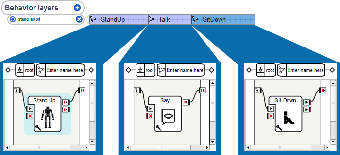
This area contains the behavior layers of the timeline, which basically represent what NAO is going to do in addition to his movements.
Each line corresponds to a behavior layer.
Here there are 2 behavior layers. One is named LEDs, the other sound.
You can add a behavior layer with the + button next to Behavior layers.
You can edit the name of a behavior layer by directly clicking on its name.
You can remove a behavior layer with the x button on the right of its name.
You can enable or disable a behavior layer by clicking on the blue round on the left of its name:

|
The behavior layer is disabled. It is hidden and will not be loaded nor executed. |
|---|---|

|
The behavior layer is enabled. |
Each blue rectangle on a line corresponds to a behavior keyframe:

You can insert a new behavior keyframe in a behavior layer by right-clicking on the frame you want to insert the behavior keyframe to and selecting Insert KeyFrame.
You can edit a behavior keyframe by double-clicking on it. You can then set its name, its start frame in the index field, and its image.
You can select a behavior keyframe simbly by clicking on it. You can select several behavior keyframes by dragging and dropping in the behavior layers area. You can select all behavior keyframes from a behavior layer by right-clicking on the concerned behavior layer area and selecting Selection > Select from layer. You can select all behavior keyframes by right-clicking on the behavior layers area and selecting Selection > Select all.
You can move behavior keyframes within the behavior layer by simply dragging and dropping them. They can also be cut, copied, pasted and deleted through the right-click menu.
Details area

The Edit button enables you to set some parameters for the timeline:
FPS: This means frame per second. It basically sets the execution speed of the timeline.
Size: This is the size of the timeline in number of frames.
Resources Acquisition: This setting enables you to manage conflicts between commands sent to the same joint. You can choose several modes:
- Passive: The motion will be done if it can be done. If it cannot, then it will not.
- Waiting: The motion will be done as soon as the joints will be available i.e. not being doing an other motion.
- Agressive Mode (unsafe): The motion will be done anyway, even if an other command has been asked on the same joint.
Warning
The Resources Acquisition setting should not be used anymore as an improved solution has been provided which enables you to set the resources used by each box and some more settings.
We recommend you to update your older behaviors and set the resources of the boxes of your behaviors. To do so, see the section How to set resources in a box.
Next to the Edit button, the number of the selected frame is indicated, when there is one.
On the right, you can see the general scrollbar of the timeline.
Timeline Editor
The Timeline Editor has two edition modes:
In both modes, there are toolbars available on the top of the window.
The first toolbar is displayed as follows:

Here are the actions you can make with this toolbar:
| Button(s) | Function |
|---|---|

|
The classical undo and redo buttons. Warning These buttons does not affect only the timeline. They affect most of the actions you made in the behavior, even those which were out of the Timeline Editor. |

|
These buttons enables you to select the edition mode:
The second mode is selected by default. |

|
Activates or deactivate the recording mode. |


|
Starts or stops the motion recording. Automatically activates the animation mode. This button is only enabled when the recording mode is activated. A recording can also stop by itself when it reaches the last frame. The recording will be done in the current range selection, or, if there is no such selection, between the start and the end frame of current timeline. |

|
Edit the recording settings. |
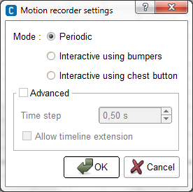
The recording settings are presented as below:

The available settings are:
Mode: The way you record joint positions. You can choose between:
- Periodic: The position of the recorded joints are regularly stored.
- Interactive with bumpers: The position of the recorded joints are stored each time you press the left foot bumper. Pressing on the right foot bumper sets the stiffness of the recorded joints.
- Interactive with chest button: The position of the recorded joints are stored each time you press the torso button or you say “store position”. NAO’s ear LEDs flash when he understands “store position”.
Time step: Time elapsing between two stored keyframes. Indeed whatever the way you record joint positions, the keyframes created at each storage will be the same time step apart.
Allow timeline extension:
If this option is unchecked, the recording will automatically stop when the end frame is encountered.
If it is checked, the recording will continue as long as the user did not press the Stop button.
In that case, the timeline contents after what was supposed to be the last frame will be “pushed” at the end of the recording.
To know how to use the recording settings refer to the tutorial: Creating a movement using the recording mode.
Whenever the recording mode is active, two additional columns appear in the table of the joints:
| Column | Description |
|---|---|

|
If this option is activated, all the children joints of this joint will be recorded. |

|
If this option is activated, all the children joints of this joint will be played during the recording. |
In both mode, you can see the list of joints and groups of joints. For example the group Legs contains the group Left leg which contains the group Left ankle which contains the joints LAnklePitch and LAnkleRoll.
To expand a group of joints, click on the + button next to its name. To unexpand it, click on the - button next to its name.
You can select a joint or a group of joints by simply clicking on it.
You can enable or disable a joint or a group of joints by clicking on the blue round on the right of its name:

|
The joint or the group of joints is disabled. It will not be loaded nor executed. |
|---|---|

|
The joint or the group of joints is enabled. |
Timeline Editor: Worksheet
The default motion recording mode is the Worksheet mode.

In this mode you see the motion keyframes of each joint and each group of joints.
Each joint and group of joints and its corresponding motion keyframes are on the same line.
Each motion keyframe that belong to a group of joints is represented by a grey rectangle when the group is not expanded and by a grey oval when it is expanded.
Motion keyframe that belong to a joint is represented by a grey rectangle.
All the keyframes are placed along an horizontal axis that indicates the frame number as in the Timeline panel.
You have the same options on motion keyframes as in the Timeline panel. And the rectangles representing motion keyframes get the same way orange when they are selected. A rectangle or an oval representing motion keyframes for a group of joints can have an intermediate greyish orange color, when only a part of their child keyframes is selected.
Moreover, you can use the option Selection > Select from layer of the right-click menu to select all motion keyframes for a joint or a group of joint.
Timeline Editor: Curves
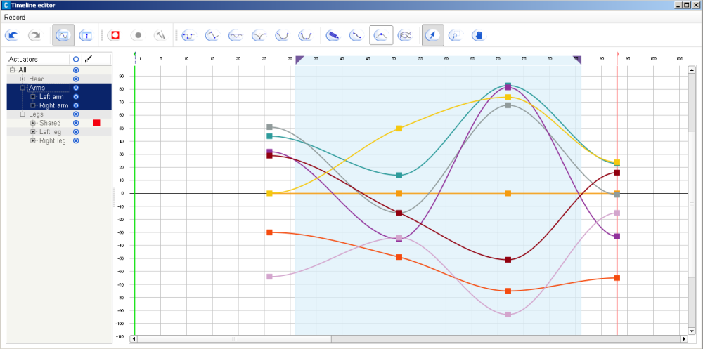
The second motion recording mode is the Curves mode. In this mode you see only the motion keyframes corresponding to the selected joints.

Each joint is represented by a curve in a different colour. You can choose the colour of each joint in the column with the following paintbrush button:

Each keyframe is placed along the horizontal axis as in the Worksheet mode. But it is also placed along the vertical axis which represents the angle value of the joint.
In the Curves mode, you can move, cut, copy and paste motion keyframes.
When this mode is activated, several buttons are added in the toolbar:
The first six buttons are used to set interpolation modes for each keyframe.
Each keyframe are linked with the previous and the next keyframe with interpolated curves.
The interpolation modes of the left and right curves of a keyframe can be adjusted.
Changing the interpolation modes will not affect the position of the key so the value and the frame will remain unchanged.
It will affect the shape of the curves depending on which interpolation mode is choosen.
Clicking on one of these buttons will set the interpolation mode for both right and left curves of the key.
Here is all the interpolation modes:

|
Constant: the value of the key is applied to the actuator up to the next keyframe. This won’t give smooth movements on the robot, but it can be used to implement “robotic movement” effects. |

|
Linear: the value is interpolated linearly toward the next key. |

|
Automatic bezier: a Bezier curve interpolation is used, but the curve parameters are computed automaticallyby Choregraphe to give smooth and good looking movements. This is the default mode for new keyframes. In that mode, contrary to all other Bezier mode, the tangents of the curve at the key are not displayed by default. They can be shown by checking the “Show tangents” button (described below). Automatic tangents, when visible, are not editable, and are displayed in blue rather than black to distinguish them easily. |

|
Bezier: this mode (and the following two) also implement a bezier interpolation, but here the curve parameters are now adjustable by the user. Two tangent handles will appear next to the key to control the curve slope. |

|
Smooth: this is a Bezier mode too, but with an additional constraint, the two tangents of the key (on the left and on the right) must be aligned. Note however that if a key is only smooth on one of its side, the constraint won’t be enforced. |

|
Symmetrical: this is similar to the Smooth mode, with another constraint: the length of the two key tangents have relative sizes, so moving one not only keep the other aligned but also moves it horizontally to have an even smoother movement. Like the Smooth mode, the symmetry constraint will only be applied if both tangents are flagged symmetrical. |
The function of the next buttons are gathered in the following table:

|
Displays the Curve key edit that is used to set key value and left and right interpolation modes. |

|
Reduce the number of keyframes in the curves and still keep a similar motion. |

|
When this button is checked, the automatic tangents of the curve that are not editable are displayed in the curve view. It is useful to mix automatic keyframes with manually adjusted ones. |

|
When this button is checked, you are in the selection mode. Drawing a rectangle with a left mouse click will select a group of keys. |

|
When this button is checked, you are in the zoom area selection mode. Drawing a rectangle with a left mouse click will zoom the view so that it fits that rectangle. |

|
When this button is checked, you are in the viewport drag mode. In that mode, the mouse cursor becomes a hand. Dragging the cursor while pressing the left mouse button will scroll the view. |
How to get the value of the time cursor of a timeline
You can access to the value of the time cursor of a timeline box from its script with the following command:
timeCursor = ALMemory.getData( self.id )
You can also access to it from the script of a child box with the following command:
timeCursor = ALMemory.getData( self.parentId )
Warning
A script box has no time cursor. So if you try to call the first command above in a script box, it will return an error.
What is a ...
Timeline of a box

A timeline is constituted by:
- a motion layer which contains movements.
- potentially one or several behavior layers which contain things NAO will do in addition to its movements.
The whole timeline is based on a time ruler.
The time is represented on the timeline by numbered frames. And each frame corresponds to a position of the robot and/or diagrams to execute.
A timeline enables you then to easily synchronize boxes with movements, movements with each other and/or boxes with each other.
When a timeline is started, the time cursor is placed on the start frame. Then it is regularly incremented to the next frame, until it gets to the end frame.
The speed to move from a frame to another is defined by the frame rate of the timeline.
Note
The frame rate can be edited by clicking on the Edit button of the Timeline panel. It is represented by the value of FPS.
Note also that this automatic process to regularly move the time cursor to the next frame can be affected (stopped, restarted, moved to another frame) by the sub-boxes and the script of the box. For example, the Goto And Stop boxes move the cursor to a specific frame and pause the cursor so that it will not move to the next frame.
Time cursor of a timeline
The time cursor represents the currently executed frame in the timeline.
Its value is the number of the executed frame.
The time cursor does not exist for a script box. Also its value is systematically equal to -1 when it is a flow diagram box or when it is a timeline box and its timeline has not been started or has been stopped.
See also: How to get the value of the time cursor of a timeline.
Frame of a timeline
The frame is the unit of a box timeline.
Each frame has a number of frame which corresponds to its position in the timeline. The frame 1 is the first frame, the frame 2 is the second, and so on.
When the time cursor gets to a frame, simultaneously:
- the joint values stored to this frame are applied to the robot.
- the diagram of each behavior keyframe placed on this frame are loaded (if they have not been loaded yet).
Start frame of a timeline
The start frame of a timeline is a specific frame.
When the timeline is started, the time cursor is directly placed at this frame.
Any frame which is before the start frame will not be reached. If you force the time cursor to move on one of those frames (with a Goto And Play box for example), this will have the same result as going to the end frame.
Note
The start frame is represented by a green flag in Timeline panel.
End frame of a timeline
The end frame of a timeline is a specific frame.
As soon as the time cursor gets to this frame:
- The time cursor is paused. So it stops being incremented.
- If there is any onStopped output:
Any frame which is after the end frame will not be reached. If you force the time cursor to move on one of those frames (with a Goto And Play box for example), this will have the same result as going to the end frame.
Note
The end frame is represented by a red flag in Timeline panel.
Motion layer of a timeline

The motion layer is where NAO’s movements are stored in the timeline.
Each frame on the motion layer corresponds to a position of the robot or a part of its body.
Note
As there are several joints stored in this motion layer, we can say it is made with several sub-motion layers, each of them corresponding to a joint. They are the sub-layers you can see when opening the Timeline Editor.
The motion layer contains motion keyframes representing specific positions set by the person who made the movement.
Then an interpolation of joint values is automatically made to obtain intermediate positions between two motion keyframes.
Note
You can choose the type of interpolation between the motion keyframes in the Timeline Editor.
Motion keyframe of a timeline
A motion keyframe represents a position of the robot or a part of its body.
It contains the angle values of the stored joints.
Note
If you leave your mouse on a motion keyframe (without clicking) the stored values will be displayed in a tooltip.
When the time cursor gets to a motion keyframe, the joint values stored to this frame are applied to the robot.
Behavior layer of a timeline

A behavior layer is constituted by behavior keyframes.
They are sequentially organized i.e. two behavior keyframes within the same behavior layer will never be active at the same time. This is because the time cursor cannot be on two frames at the same time.
To get two behavior keyframes active at the same time i.e. synchronize two diagrams, you need to put them on two different behavior layers.
Behavior keyframe of a timeline

A behavior keyframe is a diagram which is applied on a range of frames of the timeline.
As soon as the time cursor gets within this range of frames, the diagram of the behavior keyframe is loaded.
As soon as the time cursor gets out of the range of frames of the behavior keyframe, its diagram is unloaded.